 Example System / ONVIF Implementation FAQ
How to implement Relay Output (ET01)
Warning! This is an implementation hint article. Read this first.
Calling sequence
For ONVIF relay output function, the calling sequence of Genius Vision NVR can be summerized as follows:
- This sequence only applies when Event.Template (explained here) is set to ET01.
- Calls <device>GetRelayOutputs to obtain number of input and their tokens. If failed, NVR will try to call <ver10/deviceio>GetRelayOutputs. This automatic protocol version detection will be remember in an internal variable called RelayUseDevIO.
- Engage event notification sequence.
- If relay is operated by user to switch ON or OFF, NVR will call <device>SetRelayOutputState or <ver10/deviceio>SetRelayOutputState, depending on RelayUseDevIO.
Reflecting relay state change
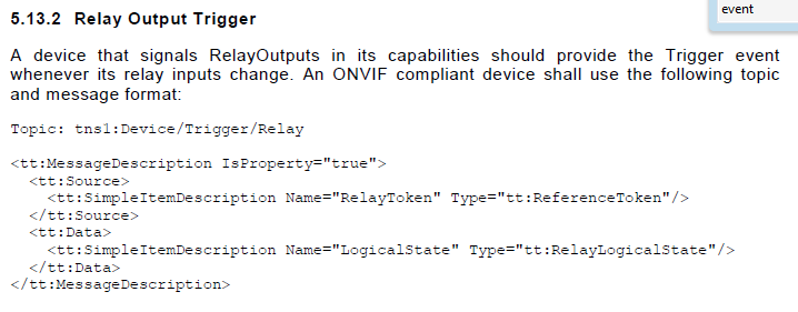
Event definition in spec
ONVIF-DeviceIo-Service-Spec-v221.pdf

Message XML example
Relay output state is reflected using notification events.
<wsnt:NotificationMessage> <wsnt:Topic Dialect="http://www.onvif.org/ver10/tev/topicExpression/ConcreteSet"> tns1:Device/Trigger/Relay </wsnt:Topic> <wsnt:Message> <tt:Message UtcTime="2008-10-10T12:24:57.321Z"> <tt:Source> <tt:SimpleItem Name="RelayToken" Value="[relayToken]" /> </tt:Source> <tt:Data> <tt:SimpleItem Name="LogicalState" Value="[relayLogicalState]" /> </tt:Data> </tt:Message> </wsnt:Message> </wsnt:NotificationMessage> |
- [relayToken]: Must match one of the tokens returned by <device>GetRelayOutputs or <ver10/deviceio>GetRelayOutputs, depending on RelayUseDevIO.
- [relayLogicalState]: active or inactive, reflecting actual relay status.
Changing relay state
- Camera must implement <device>GetRelayOutputs or <ver10/deviceio>GetRelayOutputs in order to indicate its support to relay ouptuts.
- Camera must implement <device>SetRelayOutputState or <ver10/deviceio>SetRelayOutputState in order to be able to change relay state.
- The version of spec implemented by the relay output commands must be consistent.
See also
