 Example System / Genius Vision Technical FAQ

How to use PTZ keyboard (which is External PTZ Module) and LILIN PIH-931D as an example
Note: This is an old article transiterated from this location. For informative purpose only. There is no guarantee any part of this will work on currently updated software and shall not be construed as a specification of the software.
Configuration Dialog
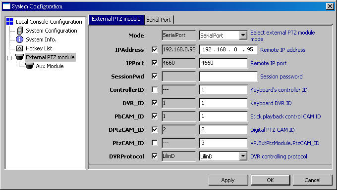
To use external PTZ module, configure it in System Configuration dialog. Most security keyboards require 2 ports to work. One for DVR control and one for PTZ control. External PTZ module and Aux Module are for different ports. Parameters are explained as following.
Mode |
disabled |
|
|
SerialPort |
Extra parameters must be configured in tab SerialPort. |
|
BF-430 |
IPAddress, IPPort, SessionPwd must be entered corerctly. |
IPAddress |
|
For BF-430. |
IPPort |
|
For BF-430. |
SessionPwd |
|
For BF-430. Leave blank if password is not required. |
ControllerID |
|
Currently not used. |
DVR_ID |
|
NVR handles the commands only when keyboard is in DVR mode and set to this ID. |
PbCAM_ID |
|
Keyboard(stick) controls playback when keyboard is in CAM mode and set to this ID. |
DPtzCAM_ID |
|
Keyboard(stick) controls digital PTZ. |
PtzCAM_ID |
|
Keyboard(stick) controls analogue PTZ. |
DVRProtocol |
|
Protocol of the keyboard. Keyboard also need to be configured. DVR and CAM modes may use different protocols. |
|
|
|
Configure SerialPort

COMPort |
Check COM port number in Device Manager of Windows. |
BaudRate |
Depends on the keyboard configuration. |
COMBuffer |
|
BitsPerByte |
Usually 8. |
StopBits |
Usually 1. |
Parity |
Usually None. |
FlowControl |
Usually Xon/Xoff. |
|
|
Configure LILIN Keyboard (PIH-931D)
Connect PIH-931D to computer

DVR and IN must be connected to 2 different COM ports.
Set protocols in NVR
For DVR port, protocol is LilinD.

For PTZ port(IN), protocol is MLP2.

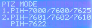
Set protocol on PIH-931D
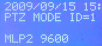
PTZ protocol must be set to MLP2(PIH-7601/7602/7610 PIH-7622).
If it's set properly, "MLP2" is shown on LED screen when moving stick in PTZ mode.

Operations of LILIN Keyboard (PIH-931D)
PTZ(CAM) Mode
To enter this mode, press SHIFT then press CAM.
To change ID, press number keys then press CAM.
In PTZ mode, stick can be used for PTZ, digital PTZ, or playback.
RIGHT |
fast forward |
LEFT |
fast backward |
DOWN |
seek forward |
UP |
seek backward |
DVR Mode
To enter this mode, press SHIFT then press DVR.
To change ID, press number keys then press DVR.
To change focused player, press number keys then press ENT.
Pause player |
|
Show live video |
|
Manual recording |
|
Fast backward (press multiple times to increase speed) |
|
Fast forward (press multiple times to increase speed) |
|
Stop player |
|
Step backward |
|
Step forward |
|
Change layout |
|
Change layout |
|
Change layout |
|
Change layout |
|
|
|


Troubleshooting and Testing Keyboard Connectivity
Due to the transient nature of serial-based communication, it could be difficult to diagnose connectivity problem until your configuration is completely correct. Therefore our system offer a keyboard debug tool that might aid the process of connection setup:
Invoke Player Control Panel to see the keyboard debug tool:

Debug box for primary port

Debug box for auxiliary (Aux) port

The content in the debug box illustrate the current state and suggest actions as below:
Debug Box Content |
Description |
Suggested Actions |
INIT |
Port initialization is not completed, most likely due to configuration error. |
Check to see if COM port name is correctly specified. Also check to see the specified COM port is not currently in use. |
OK, <N1>, <N2> |
Port is connected. <N1> is the number of bytes received. <N2> is the number of meaningful commands parsed. |
Port connectivity is established. Try to perform operations on the keyboard. Then observe:
|
Example Setup
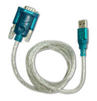
This example uses two external devices, as illustrated as below:
Device |
Device Outlook |
Description |
USB-RS232 Cable |
This cable, when connected with proper drivers installed, creates a COM port on your PC. You can use Windows Driver Manager to see which COM port it connects to. |
|
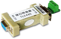
RS232-485 Converter |
This device converts RS-232 protocol to RS-485 protocol bidirectionally. If used in conjunction with USB-RS232 cable, you can connect a RS-485 device to a PC. |
Connect the devices as the block-diagram illustrated below:
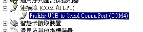
This should create two COM ports on your PC. You should be able to see what COM ports they use in Windows Device Manager. (To invoke Device Manager, use Start Menu=>Run=>"devmgmt.msc"). Suppose the two COM ports are COM3, and COM4.
Note: The COM3 and COM4 illustrated above is only an assumption. COM port numbers are dynamically assigned when the cable plug-ins to your computer. You must check the actual settings according to what your Device Manager shows. Since the two keyboard ports are not the same, you must connect two ports separately and distinguish them carefully.
Open "Cfg. Console" dialog. Enter following information to the "External PTZ module" node:
Mode |
SerialPort |
DVR_ID |
1 |
DVRProtocol |
LilinD |
(Change to SerialPort tab and enter following) |
|
COMPort |
COM3 |
BaudRate |
9600 |
COMBuffer |
2048 |
BitsPerByte |
8 |
StopBits |
1 |
Parity |
None |
FlowControl |
Xon/Xoff |


Enter following information to the "Aux module" node:
Mode |
SerialPort |
PbCAM_ID |
1 |
DPtzCAM_ID |
2 |
PtzCAM_ID |
3 |
DVRProtocol |
MLP2 |
(Change to SerialPort tab and enter following) |
|
COMPort |
COM4 |
BaudRate |
9600 |
COMBuffer |
2048 |
BitsPerByte |
8 |
StopBits |
1 |
Parity |
None |
FlowControl |
Xon/Xoff |


Use the "Debug tool" illustrated in previous section to see if data is coming in and commands is being parsed. If the <N2> is increasing then congratulation the keyboard is successfully connected to your computer with following configuration.
- Camera ID "1" correspond to playback operation on selected player of the console.
- Camera ID "2" correspond to digital-PTZ operation on selected player of the console.
- Camera ID "3" correspond to motor-based PTZ (if feature available) operation on selected player of the console.
- DVR ID "1" correspond to the NVR console operations.