 Example System / GV User Manual
Genius Vision All-in-one VMS user’s manual
- Table of Content -
Getting Started with Genius Vision VMS
Windows 7 and Hidden Tray Icon
Player (Multi-Function-Display) Capabilities
Using Online License Authorization
Windows 7 and Hidden Tray Icon
License Manager - Install package online
Alternative Way to Activate NVR
Option 1: Start by “net” command
Option 2: Start by Windows Service Manager console
Adding Cameras by Finding in Local Network
How to deal with non-standard RTSP port?
Weekly (Graphic) Schedule Configuration
Central Management Station (CMS) Introduction
How to view live and playback video in CMS system?
How to use map on the CMS system?
How to use integrated security, that synchronizes account information on all servers?
Do I need additional license to use CMS?
Can I connect to CMS server from a remote location?
Do I need a special client or server program to enable use CMS??
Can I connect to NVR of other types or vendors?
How to configure user accounts in CMS?
Can I connect to two NVRs that contains channels with the same name?
Can I connect to yet another CMS (nestable CMS configuration)?
Does the network traffic of the child NVR go through the primary NVR server?
How to configure child NVR channels?
What are the credentials used for a client to login to child NVR servers?
How should I configure my child NVRs if I want to connect from public Internet?
What are the benefits of having a primary NVR server?
Mobile Phone Video Streaming (3GPP)
Is the 3G video streaming default enabled?
How to enable 3G video streaming?
Why can't I see 3G video streaming?
How to change default web server port number?
What are the frame-rate or image size of the 3G streaming video? Can they be changed?
“Play Control” Buttons Explained
“PTZ Control” Buttons Explained
Save pattern templates and pattern sets
Part III: Intelligent Video and Advanced Topics
Activating Intelligent Detection
Activating/Deactivating Detection
Basics of region configuration
Intelligent Detection Basic Knowledge
Detect by Full-function Player
Converting Video to JPEG Stream
Legal
Documentation Copyright
This material, including but not limited to all text and graphics, is a copyrighted material of Genius Vision Inc. You should be properly authorized in order to redistribute any part of the material.
The "Software" or "SDK" are proprietary properties of "Genius Vision Inc." It is a violation of international copyright law to redistribute or reverse-engineer the software without explicit permission from Genius Vision Inc. We reserve all rights to the software except for the online evaluation demonstration purpose.
Software License Agreement
"Software" refer to software products made by Genius Vision Inc. By installing the software, you agree to be bound by this contract.
Legal Use Only
Genius Vision DOES NOT sanction use of this product toward unlawful purposes. Please check with your local regulation to make sure you are not violating any laws including but not limited to potential privacy invasion issues by using this product. Please also make sure you have the administrative access to the location you are installing this product.
Intellectual Properties
The "Software" and all related materials are proprietary properties of Genius Vision Inc. It is a violation of international copyright law to redistribute without authorization, reverse-engineer the software, modify the software, or circumvent copy-protection mechanisms.
Data Collection
You understand and consent that the client software that is installed to your computer may collect non-personally-identifiable information and transmit over the network for the purpose of monitoring system health status and enforcing licensing policies. These information includes, but not limited to, IP address, hardware configuration, OS patches/versions, OS process list, and version of software installed.
Software Upgrade
You understand that Genius Vision reserve the right to force all free software users to upgrade their software version, in case there is a flaw found later. In this case, users who choose not to upgrade may receive license revocation error.
Limited Warranty
Genius Vision develops commercial software in the hope that it will be useful. If you follow the instructions and the software is properly licensed, the software should perform substantially as described in the Genius Vision materials that you receive in or with the software.
However, Genius Vision do not guarantee the "Software" itself is free of defects or vulnerabilities. Genius Vision gives no other express warranties, guarantees or conditions. Where allowed by the laws, Genius Vision excludes implied warranties of merchantability, fitness for a particular purpose and non-infringement. If the laws give you any implied warranties, guarantees or conditions, despite this exclusion, your remedies are described in the Remedy for Breach of Warranty of this contract, to the extent permitted by the laws.
It is particularly important that you understand: it is your sole responsibility to evaluate and ensure its fitness before you put the "Software" into serious use.
Remedy for Breach of Warranty
Genius Vision will repair or replace the software at no charge. If Genius Vision cannot repair or replace it, Genius Vision will refund the amount shown on your receipt for the software. You must uninstall the software and return any media and other associated materials to Genius Vision with proof of purchase to obtain a refund. These are your only remedies for breach of the limited warranty.
If you would not agree to the terms, please do not use the software.
Getting Started with Genius Vision VMS
YOUTUBE Tutorial
The best way to getting started is to watch our YOUTUBE tutorial video.
Installation Types
You will be given choice when installing the software, as depicted in following picture:
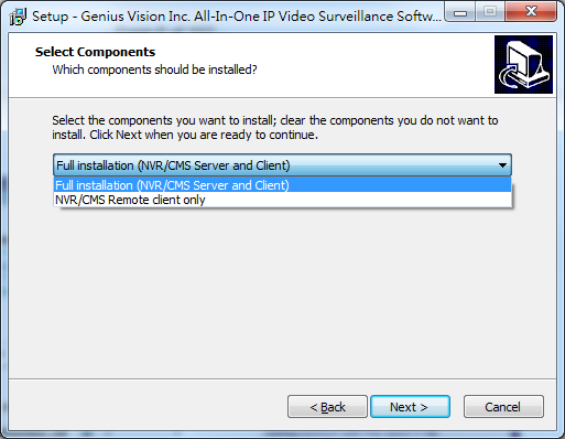
Options explained:
- Full installation: Install both NVR recording engine (the server) and client console on your computer. This will require a valid license.
- NVR/CMS Remote client only: Only install client console on your computer. The software installed with this option only equips you with the capability to connect to a NVR server on remote computer, it cannot work alone.
NVR footage player will be installed for both options. You will be able to play NVR exported footage after installation.
System Initialization
The installer will install a Windows service. You can manage it with our organizer, a triangle in Windows task-bar. When the triangle is green, you are good to go.
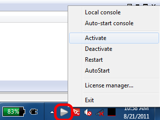
Windows 7 and Hidden Tray Icon
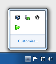
In Windows 7, tray icon is hidden by default. You have to click the white triangle to access hidden icons.
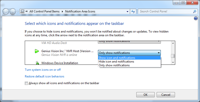
To make the hidden icon always visible, click “Customize...” and set the icon to “Show icon and notifications”.Invoke the console to interact with the server.
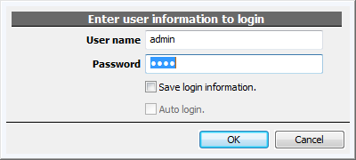
Login for the first time
Default account/password is admin/1234.
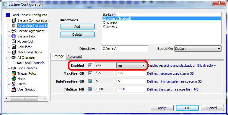
Minimum Configuration
The first thing you need to do is configuring storage. All available drives are listed automatically. Just enable the drive you want to use to store recorded data. You may want to change "MaxSize_GB" if the drive is not dedicated to recording. Everything else should be left untouched.
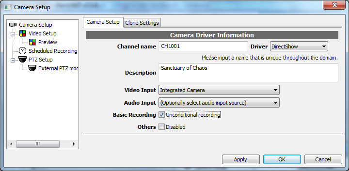
The second to do is adding a camera. Channel name is an unique identification associated with recorded data and events. It can't be changed in the future so name it carefully. Put additional information in description instead. Select driver DirectShow for webcam. Check "unconditional recording" for 24x7 recording.
Okay. Now the setup is done and the server is recording. The server is running as long as the PC is on, even before any user logged in Windows.
Check our website and YouTube channel to learn more about schedule recording, trigger policy, intelligent video, motion detection, storage report, 3GPP streaming, and many advanced functions.
http://www.youtube.com/user/cybercying#p/u
Other Useful Tips
Config camera, and many things as well, with right click menu.
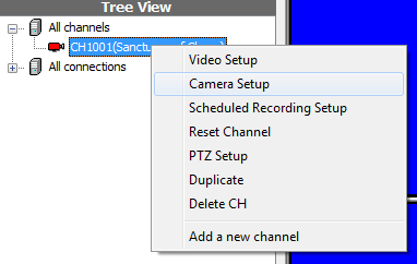
Cameras, maps, and some objects can be dragged and dropped. Experiment with various operations with mouse drag and drop.
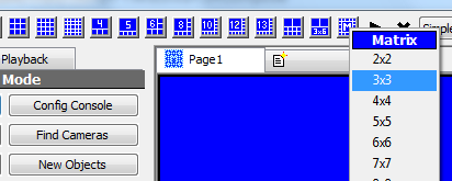
Use matrix mode for better performance. Decoding massive channels with massive resolution consumes a lot of computing power. Use simplified player (no OSD, no aspect control, no zoom, no playback, no audio) for better performance.
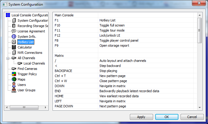
List all hot-keys.
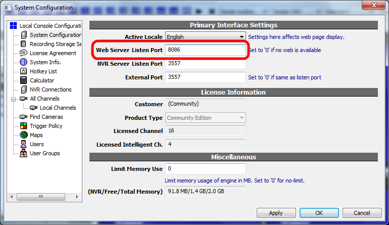
Config for IE access.
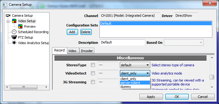
Enable intelligent video analytic on server in camera config. You don't want to do this if the server is not dedicated to surveillance. To analyze video, the engine must decode it first so it consumes fair amount of computing power.
Some of the indicators in player is clickable.
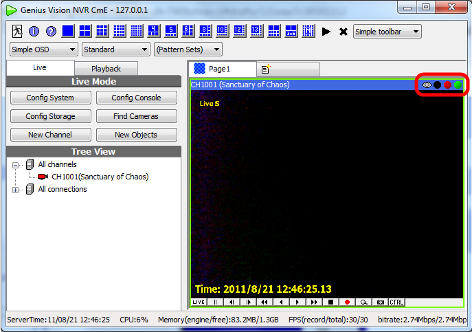
Console overview
GUI Overview
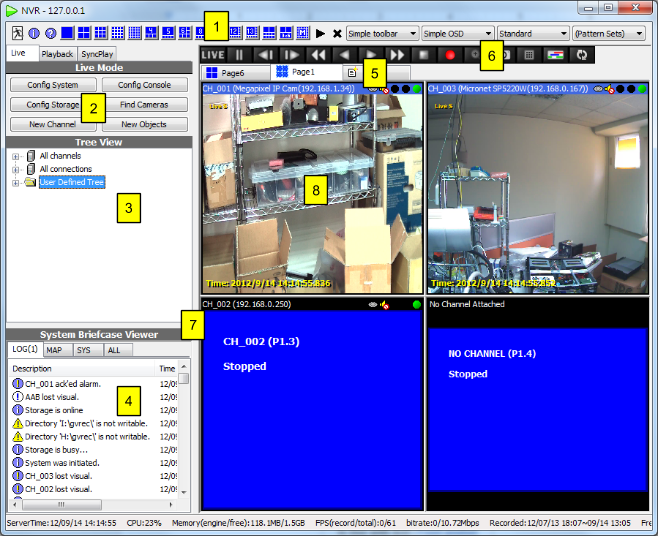
1 Layout control
|
|
|
Matrix mode. See also |
|
|
|
|
|
Logout. The local console will be closed but the system is not terminated. You will need to enter account/password to operate the system. |
2 System control
|
Operation mode
|
Live Mode
|
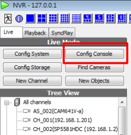
Config System, Config Console - See also Console setting Config Storage - See also Configuring Video Storage New Objects - Add a new channel, user, group, map..., etc. See also |
Playback Mode
|
Synchronized Play - See also Synchronized playback Storage Map - See also Storage report |
Synchronized Play
|
See Also |
|
From left to right respectively:
See Also |
3 User tree
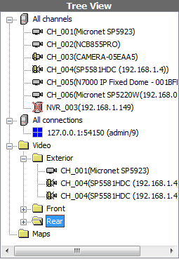
User can manage objects by creating folders and drag&drop to change the hierarchy and the order. Folders can also be renamed. Remind that the tree is global and local changes effect all remote "Genius Vision NVR" connected.
The node "All channels" are predefined and cannot be modified. Dragging a channel in "All channels" to a user-created folder creates its representatives which can be operated like the original channel item. But deleting a representative doesn't remove the channel from the system.
See Also
4 System briefcase viewer
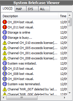
A system briefcase viewer let the users browse system objects like userlogs, channels, maps, users,.. etc. There are three components in system briefcase viewer; the filter, the header, and the list. The filter controls what types of items to be displayed. The header can be clicked to sort the items by different columns and different order. Right-click on different types of objects invokes their corresponding context menus. Items may also be dragged into players. Drag&drop behavior depends on the destined player state and the item type.
See Also
5 Pattern tab control
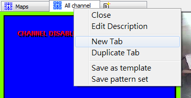
User can create and rename tabs in pattern tab control. Each pattern tab has its own layout and state.
See Also
6 Toolbar

|
View live video |
|
Pause video |
|
Step backward/forward |
|
Fast backward/forward |
|
Playback backward/forward |
|
Stop video playing |
|
Manual recording |
|
Digital zoom in |
|
Take snapshot |
|
Invoke Player Control Panel |
|
Toggle Timebar |
|
Synchronize all players. When the button is sinked, playback control of all players are synchronized. See Also |
8 Player
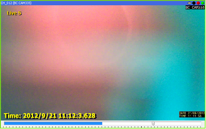
There are three components in the payer; status bar, display, and toolbar. Status bar shows the title of the channel attached and its states. The three indicators on the top-right shows if the channel is recording(red), accessing recorded data(yellow), live video(green), or alarm. The toolbar is used to control the player.
See Also
Player (Multi-Function-Display) Capabilities
Each player slot in the console has an number as their identifier. Those are P1.1, P1.2.. P1.16, etc, as illustrated below. Their function is slightly different, as illustrated in the table following the picture.
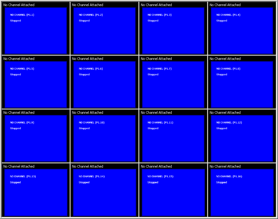
Player identifier |
Can play live & PB? |
Can view maps? |
Can view Ext. Map? |
P1.1 |
Yes |
Yes |
Yes |
P1.2 |
Yes |
Yes |
No |
P1.3 |
Yes |
Yes |
No |
P1.4 |
Yes |
Yes |
No |
P1.5 ... P1.25 |
Yes |
No |
No |
Matrix Mode
Matrix mode uses layout that incorporates simplified player. There are 2 types of player in Genius Vision NVR: full player and simple player. They can be easily distinguished by the caption (title).
Full player |
Simple player |
|
|
|
|
Optimized for |
Quality |
Performance |
OSD |
Yes |
No |
Aspect Control |
Yes |
No |
Digital PTZ |
Yes |
No |
Title (channel name, description) |
Yes |
No |
Map |
Yes |
No |
Playback |
Yes |
No |
Hybrid Layout
Hybrid layouts have one or few full players with more simple players. It’s useful to balance functionality and performance for system with limited processing power.

Using Online License Authorization
Note: This article is regarding to online licensing. Please check the new NVR Software Subscription, a more versatile and cost-effective alternative to online licensing.
Concepts
Online license authorization offers software publisher a more flexible way to sell license and to eliminate additional logistic cost. In NVR system, it even gives the flexibility to license software in per-single-channel basis. Therefore it's more cost-effective to the customers.
In our system, there are two types of license:
- Online license: This type of license requires periodic Internet check of license validity. It allows users to transfer license from one computer to another, as long as the maximum concurrent license does not exceed the purchased ones. In most scenario, this offers greatest flexibility, highest cost efficiency, and minimum risk.
- Offline license: This type of license does not require Internet when normal operation. However it needs to be "bound" to a specific computer. The operation to bind a license to a computer is called "commit". If you committed a license to a computer, it became fused to that specific computer state (including its system and the underlying hardware). If you change the underlying system or hardware, you risk losing the license.
It is generally recommended unless situation is required, one should avoid using offline license and choose the online one. Even if offline scenario is required, one should start from using online license. After a period of stable running, one can always convert online license directly to offline ones through the process of committing.
To generate effective license (called authorization code, or auth. code), one need two elements
- Request code: This code contains information about target computer, number of channels and type of product requested.
- Purchase code: This is the code that you paid money for. (Giving away this code is same as giving away your money. So you need to keep it in secret.)
In online environment, the request code is transparent (invisible) to users. You only need to input purchase code in the GUI to get authorized. However, in some special environment, where Internet access is not possible, we also offer an offline way to activate license. In this scenario, you must generate a request file (which contains encrypted request code), copy it to a portable storage device, and bring it to a computer where Internet access is available. You then connect to a vendor-provided URL (http://geniusvision.net/offline ) to upload the request file, and enter purchase code. The web-page will then generate authorization code in a file. This auth. code is generated specific for the computer on which the program generated the provided request file. It will not work on other computers. You need to copy this auth. code file back to the target computer and then import it. Please note, however, license activated in this manner implies it's an offline license and therefore cannot be transferred to another computer.
In addition to the types of license, there are some attributes associated with a specific license. Depending on actual business terms, a license might have a number of following properties:
- Forced online license: If a license has this attribute, it cannot be committed to computer. If you try to do that, it will fail (OfflineInstallForbidden). This is needed in some business terms to enforce certain licensing policies.
- Limited (Expirable) license: A license may subject to expire after certain date (either demo license or not). This kind of license implies "forced online license".
- Demo/Evaluation: If a license has this attribute, the program will display an evaluation notice stating that "using the software in production environment of any kind is strictly prohibited". This is needed for customers who want to try the software before paying. The function of the program is, however, almost same as the formal one. Demo version implies "forced online license" and "limited license" (the reverse is not true). A demo license can be transparently converted to formal one by paying fees to clear the demo flag on the server. The user only needs to restart the NVR engine to obtain formal license automatically.
Bring up License Manager
To bring up license manager, right-click on the NVR organizer. In this alternative, however, you must note following:
- You must have administrative privilege. As running license manager requires administrative access to your computer.
- On systems like Windows Vista or Windows 7, where administrative privilege is often not given in default scenario, you will need right-click NVR organizer and select "Run as administrator" to let the program gain administrative access.
- The NVR engine service must NOT be also running. That is: only one of NVR engine and License Manager can be running at the same time. They are, sort of, exclusive to each other. If you try to start NVR engine service while License Manager is running, it will cause the NVR service license check to fail.
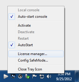
Windows 7 and Hidden Tray Icon
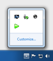
In Windows 7, tray icon is hidden by default. You have to click the white triangle to access hidden icons.
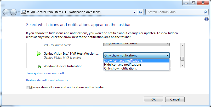
To make the hidden icon always visible, click “Customize...” and set the icon to “Show icon and notifications”.
License Manager - Install package online
The fastest and most convenient way to install package is through "Install package online" option. You will need unrestricted access to the Internet to use this option. Please note however, using this option means you will need Internet even in normal operation, as License Manager will check in the background periodically for license validation. (see Concepts.)
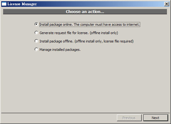
After clicking "Next", following screen will appear. You need to enter purchase code, package, and desired quantity. Please note the desired quantity must not exceed the remaining purchased quantity. If you check the "Commit to current computer" box, this will became an offline license (unless the licensing terms doesn't allow that). You can always convert an online license to an offline one later.
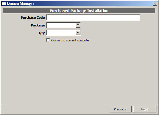
Package Types
There are 3 types of packages, when selecting license to install:
- "pro": This means the NVR Professional edition.
- "ipr": This means the NVR Intelligent edition.
- “pano”: This means the NVR Panorama edition.
The prices for different packages are different. You can mix "pro", "ipr", and “pano” packages freely on the same computer.
Managing Installed License
To manage installed license, select the indicated item:
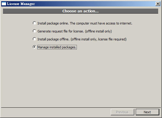
Following screen will appear:
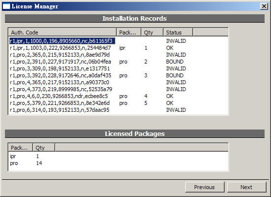
Below explains license status:
- "OK": This online license works correctly.
- "NEW": This is a newly installed license.
- "BOUND": This is an offline (committed) license which works correctly.
- "UNKNOWN": This license is currently working (and is previously known working). But due to some factors (such as lacking Internet connection or exceeding maximum concurrent license), it might soon be invalidated.
- "FAIL": This license is invalidated, mostly likely due to license check failure, or license revoked at server-side.
- "INVALID": This license is invalidated, mostly likely due to computer system change.
- "SUSPEND": This license is suspended by user. Can be reinstated.
- “RESUME”: User has requested to reinstate this license. But licensing server has not granted yet.

If you want to commit a online license to current computer, right-click on that license and bring up a context menu. Select "Commit..." to perform the commit operation. You'll need Internet connection to perform this operation.
Backup/Restore License
Sometimes if the whole system is overwritten for some reason (reinstallation of the OS) or accidentally purges the entire software installation, the license information could be gone permanently. To prevent this from happening, you need to backup the license and restore it when needed.
Note: that you can only restore license to the same system (OS+computer hardware). Restoring to different system will render the license useless.
This function is a relatively new feature. Please refer to following references:
See also
- Backup/Restore License
- Introduction to Software Subscription Licensing
 Genius Vision Software Subscription: How to sign up and begin trial?
- How to sign up for NVR Software Subscription?
Starting the service
Use the Tray Icon
The color of the tray icon indicates the system status:
Icon |
System State |
|
The NVR is offline. |
|
The NVR is online. |
|
The NVR will be auto-started very soon. |
|
The NVR is busy starting up or shutting down. |
You can right-click on the tray-icon to change the system state:
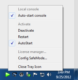
In production environment, you should configure your NVR as "Auto-start", so it will automatically start on system startup, and it will also automatically restart on abnormal shutdown.
Alternative Way to Activate NVR
The tray icon manager of the "Genius Vision NVR" should automatically appear . If it's not, you can activate the tray icon by using Windows service manager to start service "GvActiveX".
Option 1: Start by “net” command
Use "Start Menu"=>"Run"
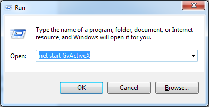
A dialog will appear. Now enter "net start GvActiveX" and press ENTER.
Option 2: Start by Windows Service Manager console
Use "Start Menu"=>"Settings"=>"Control Panel"=>"Administrative Tools"=>"Services"
Locate "GvActiveX"
Right-click and select "Start".
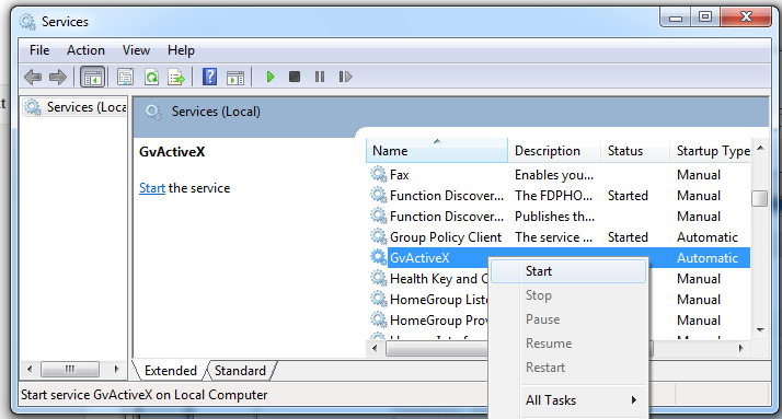
Note: Sometimes the GUI of the service manager is not updated so you will be unable to select the "Start" from context menu. In this case, press F5 to refresh the GUI.
Part I: Configuration
The section of manual will show you how to configure NVR system.
Setup for Multi-monitor
Consoles and Profiles
A profile stores states and settings associated with a local console, including the window position, layout, saved login information, IP address of server... etc. To invoke a console with specific profile, click Connect to remote NVR in Genius Vision in Start Menu. Connection Agent dialog will be opened.
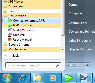
To select a profile, use the Profile combo box.

IP address of the remote server must be specified before connecting. If the server and console is on the same computer, enter 127.0.0.1 in IP address.
Click Make Shortcut... button and a shortcut will be created in windows desktop. Simply double click on the shortcut and the console with this profile will be invoked. Rename the shortcut or it may be overwrited next time a shortcut is created.

Multi-monitor
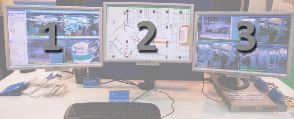
The following demostrates how to setup GV NVR for multi-monitor. The example uses 3 monitors but this can be applied to more or less monitors as well.
- Set the multi-monitor to Extended mode in Windows. This is not a requirement but it's recommended for easier setup and more intuitive operations. In extended mode, multi-monitor act as a single desktop. Just navigate the mouse cursor in different monitors to access them. For more information, refer to the manual provided by video card vendor.
- Create 3 shortcuts with different profiles. They may connect to the same NVR server or different ones. Or they may connect to local host using 127.0.0.1 as IP address.
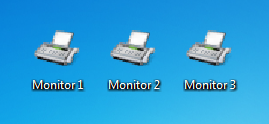
- Invoke the consoles using the shortcuts. There will be 3 windows. Move them to the monitors you want to place in and change the layout. To move among different monitors, simply move the mouse to the left/right edge of the monitor.
- For best viewing experience, close menu of some consoles by pressing F10 on keyboard.
- Next time the shortcuts are clicked, the consoles will be invoked as their last states and layouts. The shortcuts can also be placed in the Startup of Windows Start Menu.
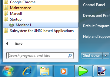
Configuring Video Storage
GUI Overview
Click on the "Config Storage". Following dialog box will appear. If no directories has been enabled, this dialog will appear automatically after login.
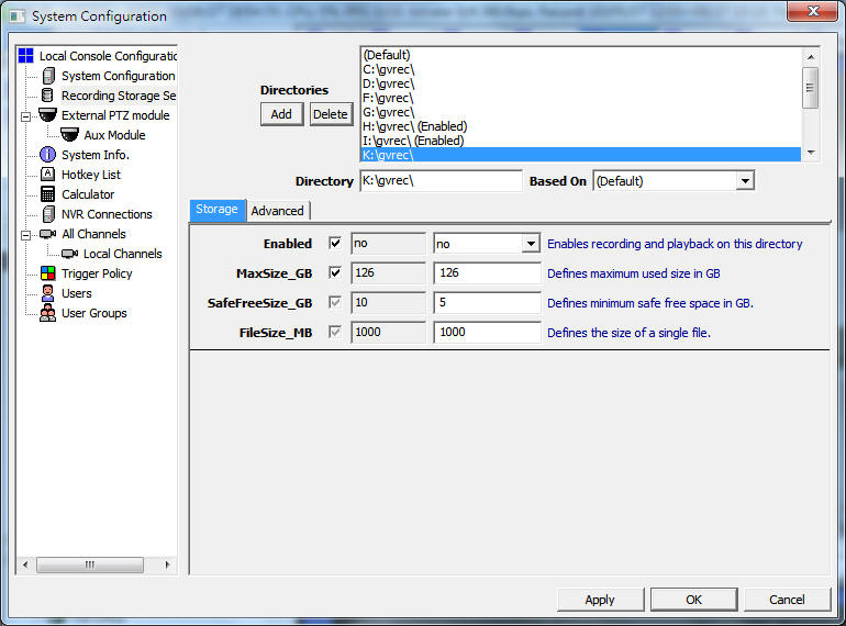
Storage Space Parameters
Parameter |
Description |
Enabled |
Is the directory enabled? |
MaxSize_GB |
Maximum space the recording process will utilize. |
SafeFreeSize_GB |
Safeguard of free space. If free space is lower than this value the system will start to recollect space from old video data. |
FileSize_MB |
The size of a single file. |
ReadCache_MB |
This is the global setting of storage system read (playback) cache. Adjust this value according to your available memory and required performance. |
WriteCache_MB |
This is the global setting of storage system write (record) cache. Adjust this value according to your available memory and required performance. |
Adding Cameras by Finding in Local Network

Click “Find Cameras” in the main console and a dialog will be invoked listing found cameras. You may have to wait for few seconds before NVR can find cameras. You can click “Scan” to reset the dialog and find again.
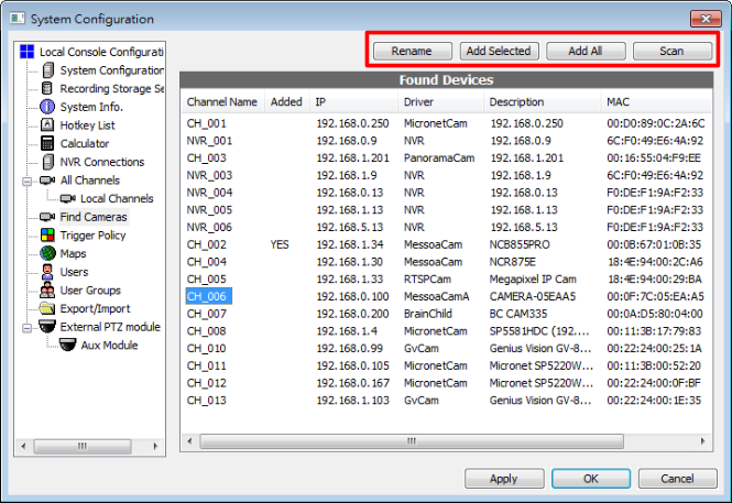
To add the camera in the NVR system, double click on the channel name (CH_001, NVR_001...). It will be added with auto-assigned channel name. If you want to change the channel name, select an entry and click “Rename”.

See also
Missing Cameras
- Camera that is in different network segment cannot be find. For example, if IP address of NVR is 192.168.0.10 and that of the camera is 192.168.2.2
- Camera that doesn’t support UPnP or the function is not enabled cannot be found. You will need to add it manually. (See also: Adding a channel)
Unsupported Cameras
For supported cameras, driver and username/password (if not changed out of box) will be configured automatically. Other cameras will be found as RTSPCam. User have to configure URL described in camera document to receive video streaming. Please refer to Adding RTSP camera.
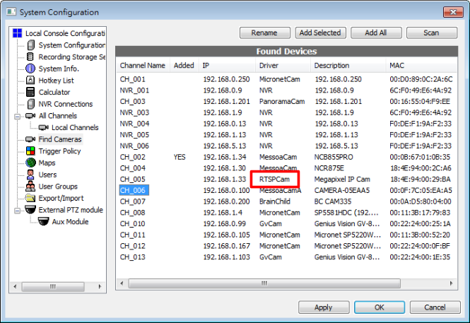
Adding a channel
Adding a channel
Right-click on the empty area of the user tree panel, and then click "New Channel…"

Following dialog box will appear.
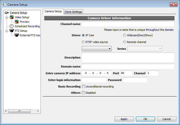
This is an integrated dialog with everything about channel configuration; camera setup, video setup, schedule recording setup, PTZ setup. Navigate through the tree nodes to change the items to be configured.
Enter the channel name, IP address, etc information.
Note: "Channel name" is an important signature of a channel and therefore cannot be changed after it's created. Nor can it be duplicated with other channels. You should choose the channel name carefully, as it associates all configuration and storage information with that channel. If you expect a more user-friendly description, you can use the "Description" field for the purpose.
Parameters
- IP Address: IP address of the network camera
- Port: The TCP/IP port number of the network camera
- Channel: The channel number of the network camera. This value may apply if a single video server has multiple channels.
- Unconditional Recording: Check this box, if you wish the NVR to start recording immediately. To configure other types of recording, you need to perform additional operations after channel creation.
- Disabled: Temporarily disable the channel. NVR will not access any channel with this box checked. You can always enable it at later time.
Adding RTSP camera
Instructions
Let's assume you have a RTSP video source as follows:
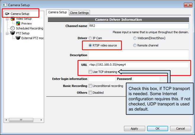
rtsp://192.168.0.55/mpeg4
In this example, you need to perform following configuration steps in Camera Setup
- Select RTSPCam as driver
- Enter correct IP address (Port is not related RTSP port)
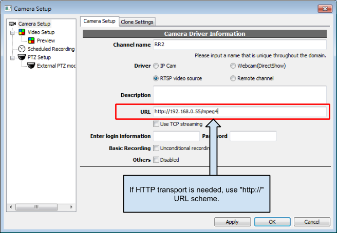
If you need HTTP transport, use “http://” URL scheme in the dialog.
Note: HTTP transport is one of RTSP underlying transport methods. This is not the same as HTTP camera.
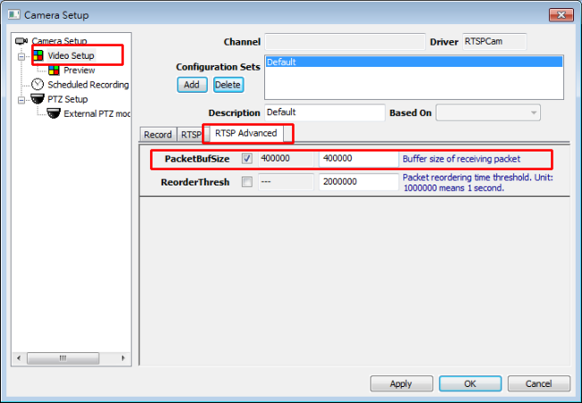
If your frame packet is extraordinarily large, you may needs this step to increase RTP buffer size (as follows):
Adding RTSP camera (Legacy)
Note: this section only applies to software version b60 or older. Camera setup dialog GUI has been updated since b70. Updated content please refer to Adding RTSP camera.
Instructions
Let's assume you have a RTSP video source as follows:
rtsp://192.168.0.55/mpeg4
In this example, you need to perform following configuration steps in Camera Setup
- Select RTSPCam as driver
- Enter correct IP address (Port is not related RTSP port)
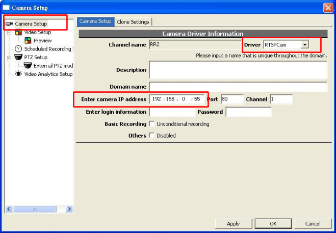
Then perform following configuration steps in Video Setup:
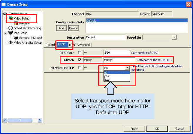
If your frame packet is extraordinarily large, you may needs this step to increase RTP buffer size (as follows):
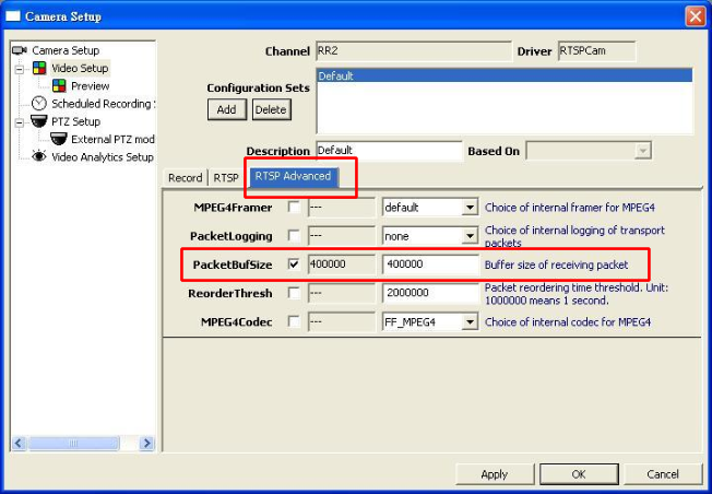
How to deal with non-standard RTSP port?
RTSP has a standard control port number 554. If you have a non-standard RTSP control port, your RTSP URL will look like:
rtsp://192.168.0.55:5510/mpeg4
When you encounter this situation, you need to change RTSPPort:
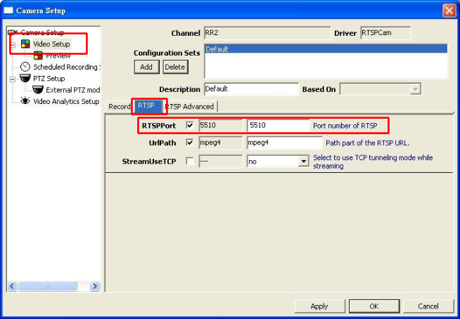
Adding HTTP M-JPEG camera
Instructions
Let's assume you have a HTTP video source that produces continuous Motion JPEG stream as follows:
http://192.168.0.55/videostream
In this example, you need to perform following configuration steps in Camera Setup
- Select HttpCamera as driver
- Enter correct IP address
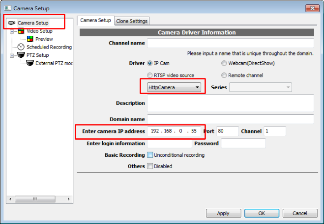
Then perform following configuration steps in Video Setup:
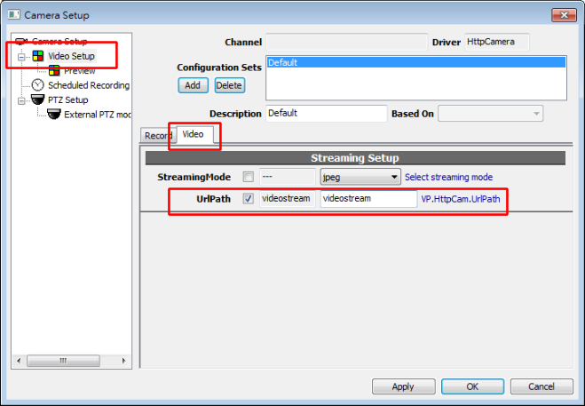
Setting Video Parameters
GUI overview
Right-click on the desired channel and select "Video setup".
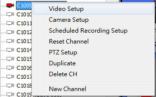
Following dialog box will appear.
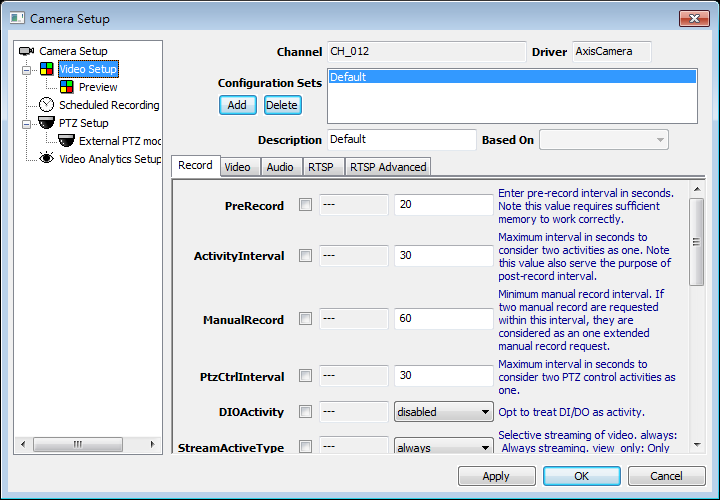
Concepts of configuration set
Each channel can be associated with multiple set of configurations. A configuration set is composed of multiple parameters. A configuration set can also "inherit" from another configuration set.
Each parameter, except for its value, can also specify its effectiveness depending on the status of the checkbox:
Effectiveness |
Description |
Icon |
Unspecified |
The value is not specified in current configuration set. The effective value depend on the inherited configuration set. |
|
Clear |
The value is "cleared" by current configuration set, meaning the parameter will not be in the effective parameter list. |
|
Set |
The value is set by current configuration. |
|
Carefully planning of configuration set can make your system extremely versatile to deal with various different situations. Especially note that the schedule config can associate to a specific configuration set.
The meaning of each parameter can differ from various vendors of IP cameras. You can refer to the description beside the parameter or look for vendor manuals for further information.
Schedule configuration
GUI overview
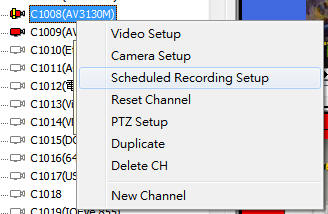
Schedule Types
Scheduled configuration items has various types, including whole day, daily, weekly (detailed), weekly (graphic), disabled. You may add multiple items.
Type |
Description |
24x7 |
24 hours recording |
Daily |
Daily fixed interval . For example: daily 08:00:00 to 21:30:00. |
Weekly (Detailed) |
Resembles "Daily", but you may appoint to days within a week. For example: Every Monday, Wednesday, Friday 08:00:00 to21:30:00 |
Weekly (Graphic) |
Weekly schedule. Each slot is united an hour. |
Interval |
Fixed interval, each starts with offset every X seconds, lasts Y seconds. |
Disabled
|
Disable current schedule item. |
Weekly (Graphic) Schedule Configuration
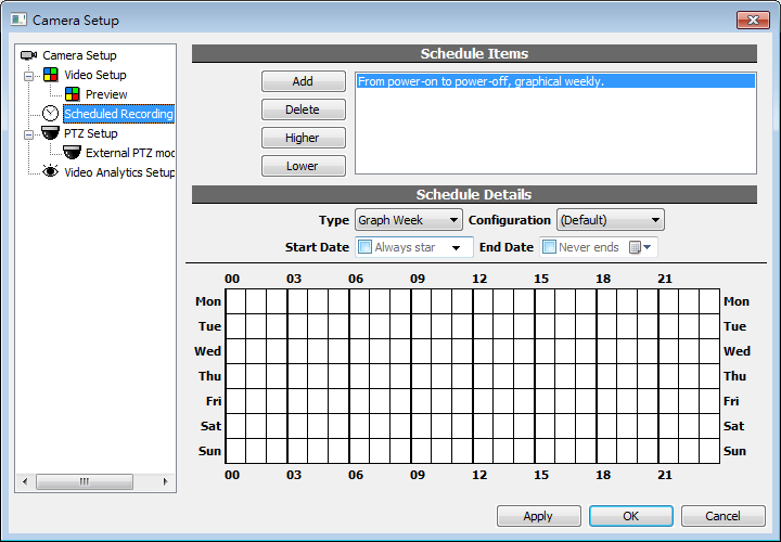
Horizontal axis is time, with hour as the unit. Vertical axis is day in a week. Click to change the schedule status. Blue means enabled, white means disabled. Click any cell and drag will copy the state of the clicked cells to others.
Scheduled Video Configuration
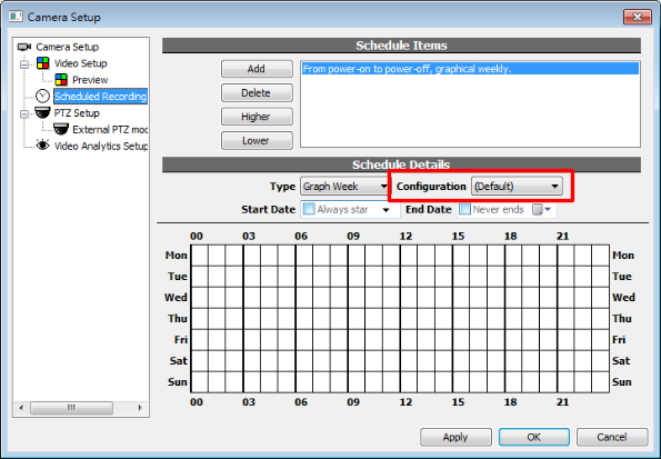
You may specified a Video Parameters for each schedule configuration item . When that item is activated during appropriate time, the specified parameter will be used. If you choose (Default) for the value, schedule configuration will not affect video parameters.
When multiple schedule configuration item is in effect, the higher (in order) one will apply. To change the priority of the items, use Higher and Lower buttons.
Permission control overview
Concepts
The permission control in "Genius Vision NVR" is group-based. The administrator configures permissions for groups, and then assign the user to one or more groups. Permissions are not assigned directly to the user, but rather associates to the user through groups.
Permission Types
Type |
Description |
System admin |
Allows to control system-level configuration, such as permissions or creating a channel. |
System operation |
Allows creating or deleting a channel, editing maps and files. |
All channel permissions |
Configures permissions to all channels. |
Specific channel permissions |
Configures permissions to specific channels. |
Channel live video |
Allows to view live video |
Channel playback |
Allows accessing archived (playback) video. |
Channel operation |
Allows to operate on PTZ, manual recording, or channel resetting. |
Channel administration |
Allows to change settings. |
Adding a user
GUI overview
Following dialog box will appear. Please click on Users tree node, it will expand automatically.
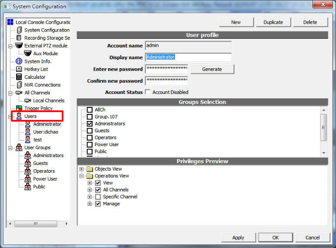
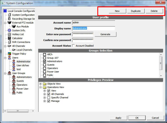
If you want to create, delete, or duplicate a user, use the buttons on the top area.
Adding a group
GUI overview
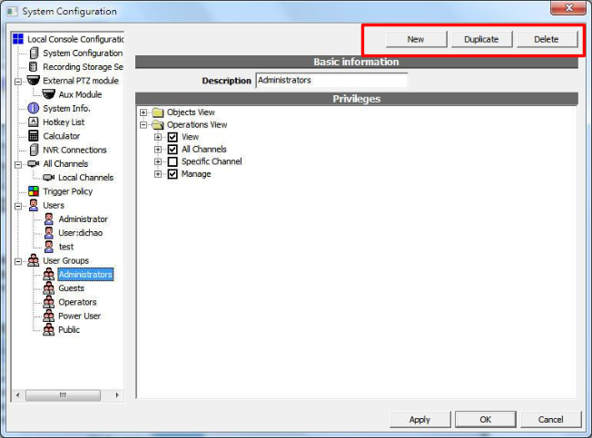
Following dialog box will appear. Click on the “User Groups” tree node and it will expand automatically.
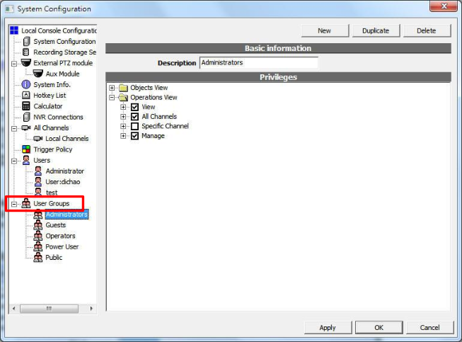
You can check the privilege you wish to grant to the group.
If you want to create, delete, or duplicate a user group, use the buttons on the top area.
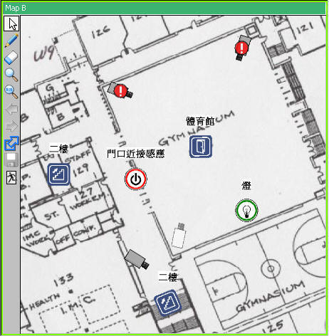
Creating Maps
Create New Map
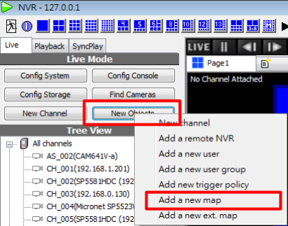
Select Add a new map in menu of New Obj. The map can be draged into User tree and be operated as it is in system briefcase viewer. To view the map, drag it in a player. Not all players support maps.
See also
GUI overview
Toolbar Functions
Icon |
Description |
Icon |
Description |
|
Enter map viewing mode |
|
Restore 1:1 view of map |
|
Enter map editing mode |
|
Map properties |
|
Enter delete object mode |
|
Map hyperlink |
|
Enter map panning mode |
|
Save changed map |
|
Zoom-in map |
|
Exit map editor |
Adding Items
Item Type |
Add Item Instruction |
Bitmap |
Drag a JPEG/BMP file in the map. Or drag a previously uploaded file from system briefcase viewer. |
Channel |
Drag channels from system briefcase viewer or user tree. |
Hyperlink |
Assuming you want to add the link of map A in map B. 1. Open both map A and map B in players. 2. Adjust the view of map A with zoom in/out. 3. In the toolbar of map A, drag Map hyperlink icon to map B. |
IO port |
Drag IO ports from system briefcase viewer or user tree. |
Basic Operations of Objects
Right-click on any types of map objects, following context menu will appear. Not all operations are available for all objects.
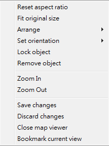
Reset aspect ratio
Reset the object to its original aspect. Only applies to Bitmaps.
Fit original size
Reset the object to its original size. Only applies to Bitmaps.
Arrange
Arrange the object's display order(Z order). "Back" objects covered by "front" objects are not visible.
Set orientation
Set orientation of the object to 0/90/180/270 degrees.
Lock object
Position/size/direction of a locked object cannot be changed. Its "property" dialog is still accessible if available for that object type.
Properties
Invoke the property dialog to edit additional information such as description or stereotype(icon). Only applies to hyperlink and IO port.
Remove object
Delete the map object.
Note: that only the map object is deleted. The entity the object represents to will not be deleted.
Mouse operations
|
Rotate/resize |
|
Move |
|
Resize |
Special operations
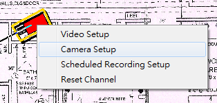
Channel operation
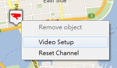
You can perform channel configuration through map by right-click on channel icon.
See also
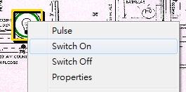
IO port
You can perform I/O port operation (switch on/off, pulse, etc) through map by right-click on I/O port icon.
See also
External Maps
Warning: This function is deprecated. See Issue: Google Map no longer working
Create New Map
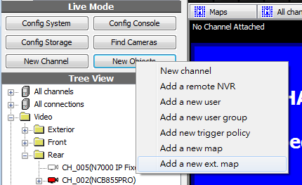
Select Add a new ext. map... in New Obj menu. The map can be draged into User tree and be operated as it is in system briefcase viewer. To view the map, drag it in a player. Not all players support external maps.
See also
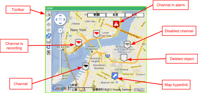
Toolbar Functions
Icon |
Description |
|
Enter map viewing mode |
|
Enter map editing mode |
|
Added a bookmark of current map and current view in system briefcase. |
|
Save changed map |
|
Reloading the map from map server. Any unsaved changes will be discarded. |
|
Exit map editor |
Basic Operations - Zoom In
Use mouse wheel or click the scale bar on map.

Change Map Type

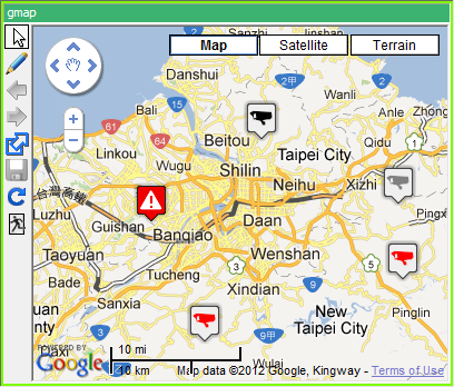
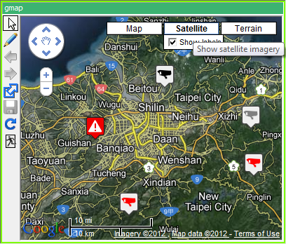
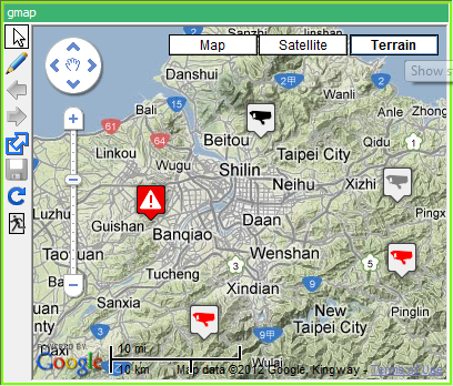
Adding Items
Item Type |
Instructions |
Channel |
Drag channels from system briefcase viewer or user tree. |
Hyperlink |
Drag a map hyperlink from briefcase viewer or from internal map viewer. |
IO port |
Currently unsupported. |
Basic Operations of Objects
Remove object |
Object can only be removed in editing mode.
|
Special operations
Channel operation |
See also |
Trigger Policy
Adding New Trigger Policy
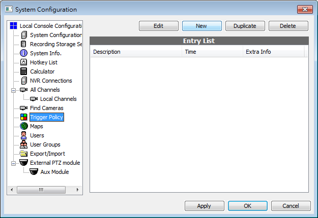
In System Configuration dialog, click Trigger Policy tab.
Click New to add a trigger policy. There can be multiple entries of trigger policy.
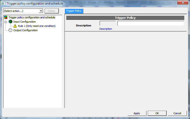
Input Configuration
Item type |
Description |
Channel trigger |
Triggered by channel events such as video loss, alarm, IO port... etc. |
System trigger |
System events such as system start, system config change... etc. |
Schedule trigger |
Triggered at specified time. |
Output Configuration
Item type |
Description |
Channel control |
Recording, IO control, PTZ control |
Send Emails |
|
FTP |
Upload file to FTP server |
Channel trigger
Value |
Description |
on |
IO on |
off |
IO off |
vloss |
video loss |
vreturn |
video recovered |
disabled |
disabled |
enabled |
enabled |
record |
is/start recording |
nrecord |
not/stop recording |
alarm |
alarm triggered |
alarm_progress |
alarm in progress |
alarm_tamper |
Tamper detected (IVS) |
alarm_foreign |
Foreign object is detected (IVS) |
alarm_missing |
Missing object is detected (IVS) |
alarm_tripwire |
Tripwire is crossed (IVS) |
nalarm |
alarm dismissed |
Schedule trigger
See also
System trigger
Value |
Description |
any_vloss |
any video loss |
system_start |
system start |
error_restart |
system start after error shut down |
system_config_change |
system config changed |
channel_config_change |
any channel config changed |
Channel control
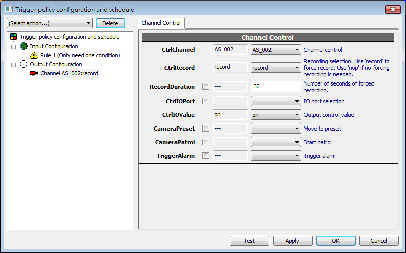
Field |
Description |
CtrlChannel |
The channel to control |
CtrlRecord |
Recording selection. Use 'record' to force record. Use 'nop' if no forcing recording is needed. |
RecordDuration |
Number of seconds of forced recording. |
CtrlIOPort |
IO port selection |
CtrlIOValue |
Output control value |
CameraPreset |
Move to PTZ preset |
CameraPatrol |
Engage PTZ patrol |
TriggerAlarm |
Trigger specific type of alarm |
See also
- Mobile push (Note: This function is available since version 920)
- NOTE: This function has been superseded, you are strongly recommended to use Mobile push instead, which is available since version 920.
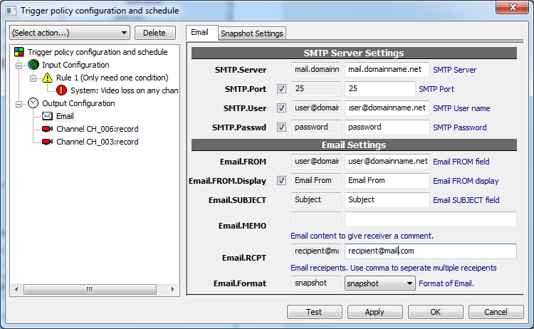
Required parameters
Field |
Description |
SMTP.Server |
IP or domain name of SMTP server |
SMTP.Port |
Port, usually 25 |
SMTP.User |
User name to log in |
SMTP.Passwd |
Password to log in |
Email.RCPT |
Recipients. At least one is required. Separate multiple recipients with ';'. |
Snapshot (Email)
- NOTE: This function has been superseded, you are strongly recommended to use Mobile push instead, which is available since version 920.
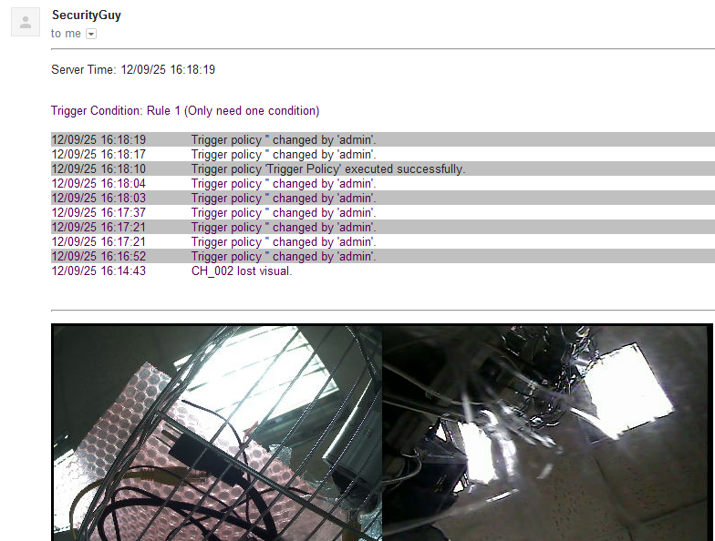
If "Email.Format" is set to "snapshot" and one or more channel control exist in this policy, a snapshot of the channels is attached to the email. Multiple channels will be composed as a single snapshot automatically. The dimension and quality of the snapshot can be configured in Snapshot Settings tab.
FTP
- NOTE: This function has been superseded, you are strongly recommended to use Mobile push instead, which is available since version 920.
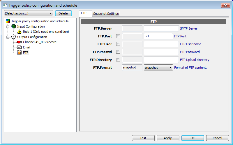
Required parameters
Field |
Description |
FTP.Server |
IP or domain name of FTP server |
FTP.Port |
Port, usually 21 |
FTP.User |
User name to log in |
FTP.Passwd |
Password to log in |
Snapshot (FTP)
Snapshot is composed as it is in email.
Trigger policy logics
Multiple trigger conditions can exist in a single trigger rule. Action is done only when all or some of the conditions are met, depends on AND or OR logic being applied. Logic OR is always applied to the first rule. Logic AND is applied to any added new rule.
Central Management Station (CMS) Introduction
Overview
In the past, Genius Vision NVR client (console) can connect to only one remote server. All operation are restricted to single remote server. With the new CMS architecture, users are allowed to connect to multiple NVR servers simultaneously. Users are also allowed to perform live, playback, map, configuration across multiple servers at the same time.
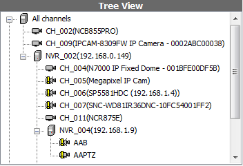
Example of CMS tree view
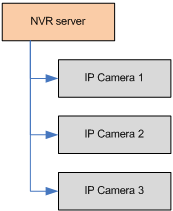
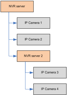
To understand how it works, just think of a NVR connection as a IP camera channel, with the difference that a NVR connection expands to one or more IP cameras. Illustrated in the following diagram:
|
|
Original architecture |
CMS architecture |
With the new CMS architecture and careful project designing & planning, a fairly scalable system can be constructed, as illustrated below:
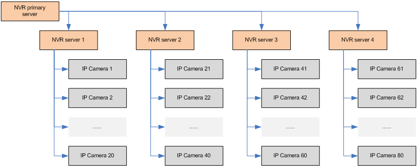
Mid-scale Surveillance System Diagram
Primary NVR server
For the CMS architecture to work, there need to exist a primary NVR server, which holds the information of other NVR servers (like the diagram above). This server will be the server to connect when client is connected from a remote site.
This primary NVR server is sometimes referred to as the "CMS server".
Synchronizing User/Group Information
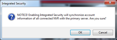
For middle to large scale system, managing user accounts and their passwords could also be a challenging task. Therefore our CMS architecture offers "integrated security", meaning that the administrator could opt to synchronize all account information to the primary server. This spares administrator the effort to manage different user names of different servers.
How-tos
Here's a of list quick questions that might help you to find the information you need:
- How to add a NVR connection?
- How to view live and playback video in CMS system?
- How to use map on the CMS system?
- How to use integrated security, that synchronizes account information on all servers?
- Do I need additional license to use CMS?
- Can I connect to CMS server from a remote location?
- Do I need a special client or server program to enable use CMS??
- Can I connect to NVR of other types or vendors?
- How to configure user accounts in CMS?
- Can I connect to two NVRs that contains channels with the same name?
- Can I connect to yet another CMS (nestable CMS configuration)?
- Does the network traffic of the child NVR go through the primary NVR server?
- How to configure child NVR channels?*
- What are the credentials used for a client to login to child NVR servers?
- How should I configure my child NVRs if I want to connect from public Internet?*
- What are the benefits of having a primary NVR server?
- Mob
How to add a NVR connection?
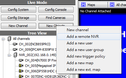
Click "New Object" and select "Add a remote NVR".
Following dialog will appear. Each field is described as following paragraph.
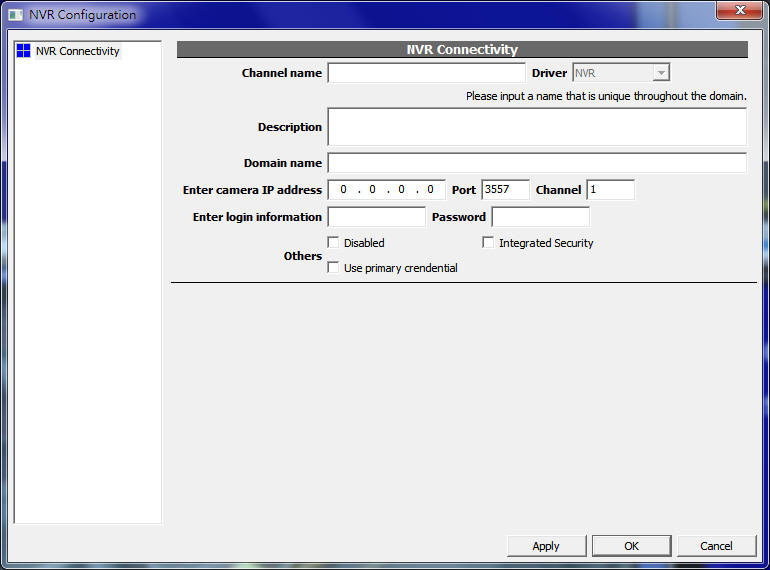
Field |
Description |
Channel name |
The channel name of the NVR connection. Please note this name shares the same name-space of IP camera channel names. It has to be unique from all existing channel names. |
Description |
Description of this connection. |
Domain name |
Optionally supply the domain name of the host address. |
IP address |
IP address of the host address. |
Port |
TCP port of the server. Default is 3557 if not otherwisely changed. |
Login information |
Login credentials to the NVR server. |
Disabled checkbox |
Check to disable the connection. |
Integrated security checkbox |
Check to enable integrated security, which will synchronize all account information to the primary server. |
Use primary credential checkbox |
Check this to use the same client-supplied password to connect to this NVR connection, rather than the connection-supplied password. Checking this box is generally considered more secure than non-checking. (See What are the credentials used for a client to login to child NVR servers?) |
See also
- Can I connect to two NVRs that contains channels with the same name?
- What are the credentials used for a client to login to child NVR servers?
How to view live and playback video in CMS system?
Viewing live and playback video on CMS is no different than using it on NVR. Please refer to following links for more details.
How to use map on the CMS system?
Using map on CMS is no different than using map on NVR. Please refer to Creating maps for more details.
How to use integrated security, that synchronizes account information on all servers?
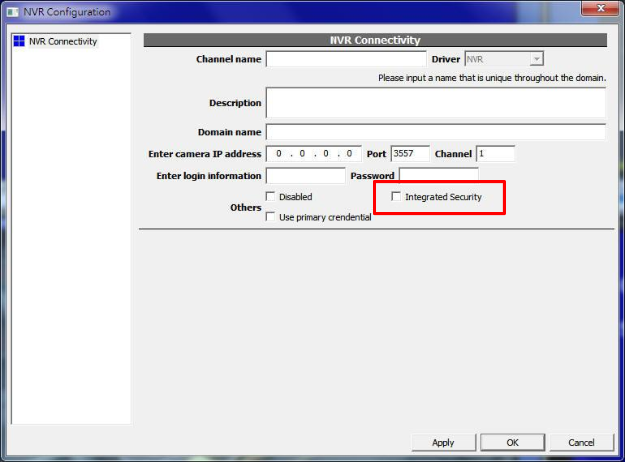
In the NVR connectivity configuration dialog, you must check the "Integrated Security" checkbox. Enabling this checkbox will cause all account information be synchronized.
Do I need additional license to use CMS?
Yes.
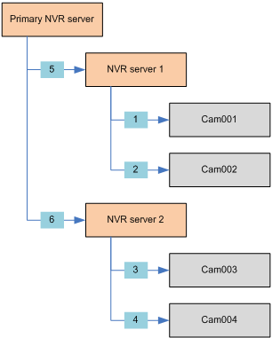
Each NVR connection is similar to one IP camera connection. Therefore for each NVR connection you need additional one channel license. Only professional edition and intelligent edition qualifies the use of CMS.
Let's use an example scenario in the following diagram. A primary NVR server connects to 2 child NVR servers, which individually has two IP cameras connected. The small blue box highlights the license requirements. This example requires 6-channel license installed in a way that Primary NVR server has two channels, NVR server 1 has two channels, and NVR server 2 also has two channels.
Can I connect to CMS server from a remote location?
Yes.
Genius Vision CMS server is no different than the NVR server. Genius Vision CMS client is also the same as the NVR client. All operations, including maps, alarm processing, live & playback, permission control, can all be performed from a remote location.
This offer great flexibility when planning a complex project. For more information, please refer to What are the benefits of having a primary NVR server?.
Do I need a special client or server program to enable use CMS??
No.
CMS feature is tightly integrated into original NVR client/server architecture. No special software is required to enable this feature.
You do, however, need to use a sufficiently new version of software that comes with the CMS feature, both for client and server.
Can I connect to NVR of other types or vendors?
No.
Only Genius Vision NVR Professional Edition or above is and will be supported in CMS architecture.
How to configure user accounts in CMS?
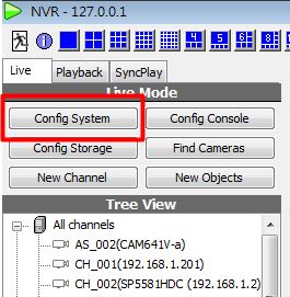
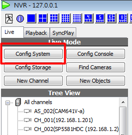
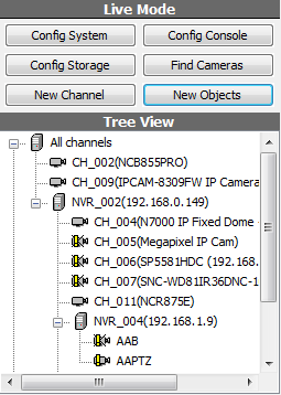
In the main console left panel, click "Config System", like the following picture:
Following system configuration window will appear.
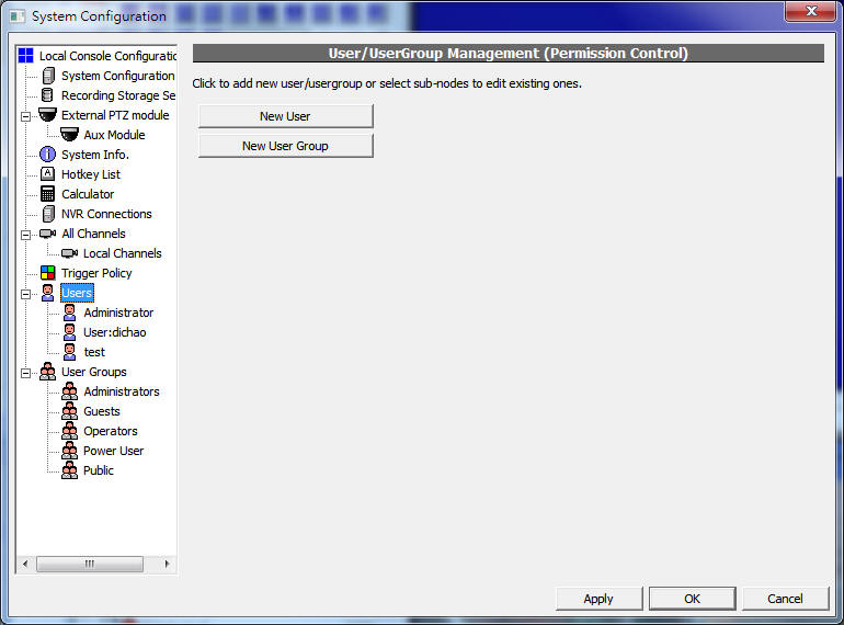
Click on the "Users" node as highlighted in the picture above. All users and groups will expand immediately.
You may then click on the specific user or group to modify their information. Or you can click "New User" or "New User Group" to create new users or new groups. For more detailed information about permission control, please follow links below:
Can I connect to two NVRs that contains channels with the same name?
Yes but not recommended.
As the channel name must be unique throughout the domain (the entire domain that is reachable from the primary NVR server), connecting two NVRs with some channels having the same name causes name conflicts.
Our system has a way to automatically resolve name conflicts, in order to make the system to continue functioning properly. However, such conflicts will render only one of the channels with the same name usable. Thus all accessible channels keeps their names unique throughout the domain. (This is how we call that one channel is obscured by another, rendering it inaccessible, due to duplicated names).
Though the system is equipped with automatic resolution of name conflicts, configuring your system with duplicated channel names is highly unrecommended. Such configuration could easily causes user misunderstanding.
This can be illustrated in the following diagram. In this example there are two cameras both named "Cam001". As a result of name conflict, the CMS will only be able to access one of them, the "Cam001" inside "NVR server 1". The "Cam001" inside "NVR server 2" will not be accessible (hidden) from user. (Unless the first Cam001 is removed from "NVR server 1", or the "NVR server 1" is removed from the CMS)
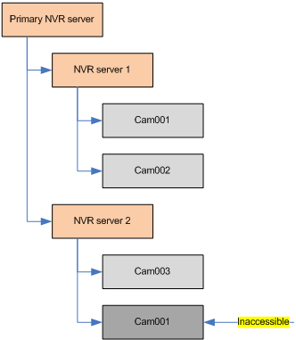
Obsecured channel
Can I connect to yet another CMS (nestable CMS configuration)?
Yes but not recommended.
Our CMS architecture fully support nested configuration. (as illustrated below)
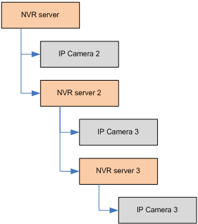
Nested CMS configuration
However such configuration is not recommended. As it would easily cause user misunderstanding.
From previous Q&A, we know that each channel name must be unique throughout the domain. Configuring nested CMS structure could potentially extend the domain without the inner domain knowing.
Does the network traffic of the child NVR go through the primary NVR server?
No.
Network traffic, such as live or playback video, goes directly from child NVR into the client. They do not consume any primary NVR server bandwidth.
From this point of understanding, the child NVR must be in a network domain that is directly accessible by the client console, otherwise video could not be viewed.
How to configure child NVR channels?
Follow the instruction below:
Firstly, invoke "Cfg. System" dialog and switch to the "NVR Connections" node.
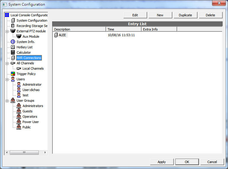
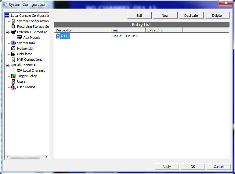
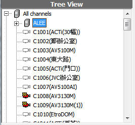
Select the target child NVR (in this example, the child NVR called ALEE), and click "Edit".
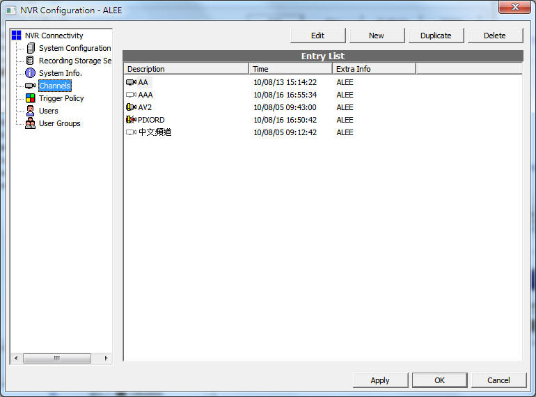
After clicking "Edit" in previous screen, a second configuration dialog pops-up. This is the child NVR configuration window. Now click to the "Channels" node. You are now able to perform all channel configuration operations in this child NVR.
What are the credentials used for a client to login to child NVR servers?
There are two types of NVR connection, in the sense of the credentials used. To illustrate this, let's suppose we have a CMS structure as follows:
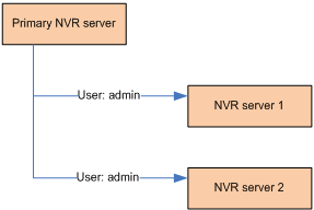
The two child NVR connection is configured to connect as "admin", which usually has the highest privillege. This kind of configuration is usually a necessary scenario because the primary NVR server needs to have enough access to the child NVR to perform management tasks.
However when a user logon, there could be two kinds of scenarios, described in the following table (notice the yellow highlighted differences) :
Scenario 1: Use user supplied credentials
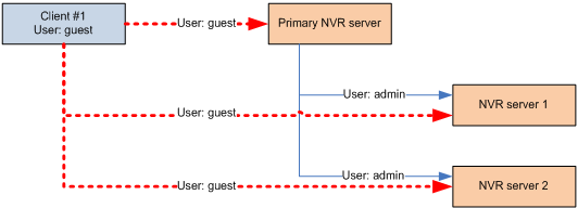
Pros: Higher security
Cons: More difficult to configure.
Scenario 2: Use connection supplied credentials
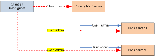
Pros: Easier to configure
Cons: Lower security
Because of the existence of the two possibilities, an option exist to let the administrator to choose the type of connection when setting up a child NVR connection, the "Use primary credential" checkbox in the NVR connectivity dialog:
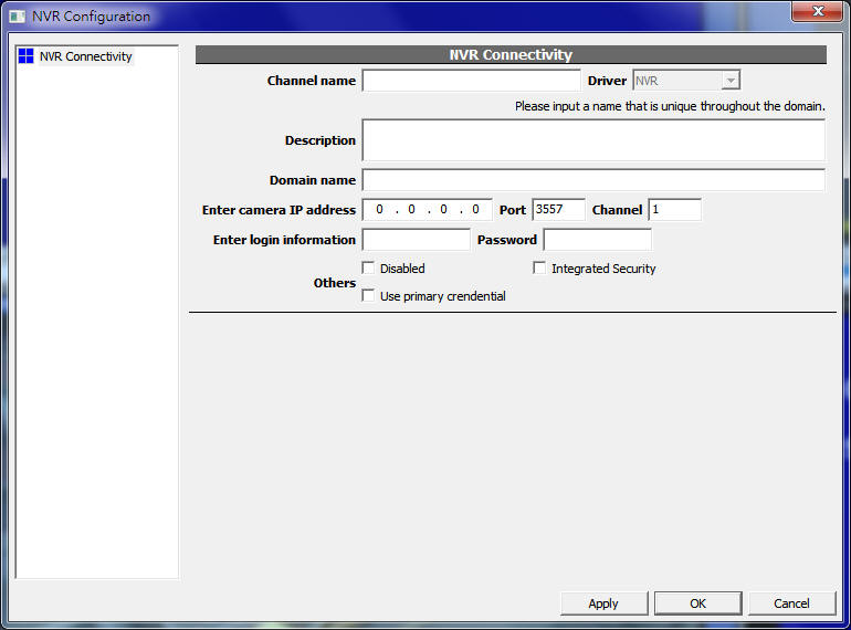
When the checkbox is checked, the connection uses "Scenario 1: Use user supplied credentials", when it's unchecked, "Scenario 2: Use connection supplied credentials" is used.
How should I configure my child NVRs if I want to connect from public Internet?
This is an advanced topic. Audience should have moderate network configuration experience.
Please read the two Q&A before continuing this topic.
- Does the network traffic of the child NVR go through the primary NVR server?
- What are the credentials used for a client to login to child NVR servers?
If you would like to configure your system to be publicly accessible, then all NVR nodes in your system should have public IP addresses. This is because a client connects to child NVR directly, rather than passing-through the primary NVR:

Configuration
Note that IP cameras connected to child NVRs are allowed to configured to private IP, while still accessible by remote client. This is because client accesses IP camera (live/playback, etc) through NVR. This is what happens when client actually connects to the system:

Following is an incorrect configuration example:

Note in this example, NVR server 1 and 2 are configured as private IP address. This will make client have trouble connecting to the IP camera inside:

However if a client is connecting from inside the private network, then this configuration is workable:

What are the benefits of having a primary NVR server?
Genius Vision defines CMS architecture by requiring a primary NVR server. This architecture has some advantages over those that does not require one:
- CMS can be remotely accessed: Metadata like maps or trigger policies can be stored in a central location. User can logon to CMS from any remote computer and still be able to access to the preconfigured map data with rich GUI.
- CMS run as a server monitor: This architecture treats the CMS server a daemon process (without GUI) that runs in background. So even when no user is monitoring anything, the daemon process can still be configured to monitor events by rules. This provides great flexibilities to plan complex projects.
- Architectural uniformity: Such architecture is directly extendable from original client/server architecture. Our system can scale from a single computer (self-fulfilled client/server) into a large-scale multi-location enterprise system, all in the same architecture. Such architecture reduces the possibility that some functions are used less than others because they are only used in large-scale system, and thus lack proper testing.
Mobile Phone Video Streaming (3GPP)
Overview
If you have a mobile phone that is compliant to 3GPP standard, then you can now use it to connect to our NVR to see live video streaming.
If your system is properly configured to support 3G video streaming, you will firstly use your browser to enter the URL to your NVR in the form:
- http://<ip_to_your_nvr>:8086/
Note: The "8086" is the default port number of the NVR built-in web server, the one that also serve Internet Explorer. This can be changed from system configuration.
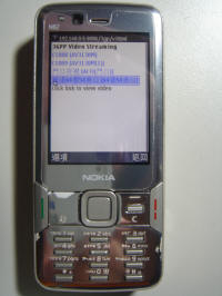
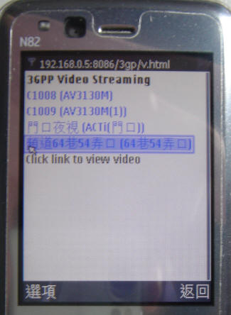
Step 1. Enter first page, list all channels available. |
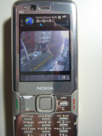
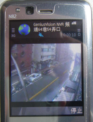
Step 2. View video streaming. |
|
|
|
|
How-tos
Here's a of list quick questions that might help you to find the information you need:
- Is the 3G video streaming default enabled?
- How to enable 3G video streaming?
- Why can't I see 3G video streaming?
- How to change default web server port number?
- What are the frame-rate or image size of the 3G streaming video? Can they be changed?
Is the 3G video streaming default enabled?
No.
3G video streaming involves potential video transcoding. It has to be enabled in the server before you can really use it. Also, be informed that enabling this feature consumes certain resource (though not much) on the server.
How to enable 3G video streaming?
To enable 3G video streaming, open "Video Setup" of a designated channel. On first tab "Record", scroll down the page to look for attribute "3G Streaming".
There are three options:
off |
3G video streaming is disabled. |
on |
Turn on the 3G video streaming, using MPEG-4 codec. |
h264 |
Turn on the 3G video streaming, using H.264 codec. |
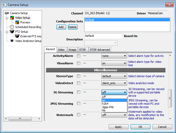
If the 3G video streaming is successfully enabled, a small "3G" will appear beside the camera icon, indicating 3G transcoding is activated:
Why can't I see 3G video streaming?
There could be a number of reasons. Firstly, your mobile phone must support 3GPP standard for this function to work. Secondly, when the mobile browser tries to reach NVR web server, it will automatically determine the phone type. If this detection is not successful, you may not be redirecting to the correct page. In this case, enter the following URL:
- http://<ip_to_your_nvr>:8086/3gp/v.html
If you still can't see video streaming, please contact our technical support, with your mobile phone model number (or device) available to us for testing and diagnosis.
Unsupported Mobile Devices
If your mobile device doesn’t support 3GPP standard, you can use our more generic feature called “JPEG streaming” that could convert all video streams into industry standard JPEG/HTTP streams that can be rendered on almost all mobile browsers.
See Also
How to change default web server port number?
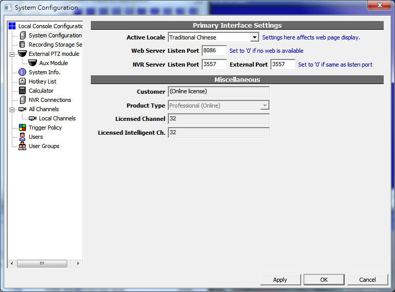
Invoke "Config System" dialog and change the value as indicated in the following picture:
What are the frame-rate or image size of the 3G streaming video? Can they be changed?
The image size and frame-rate is currently fixed at 320x240, 5 frames-per-second.
There is currently no GUI offered to change these settings. You can only choose to enable this feature or not.
Part II: Operation
Viewing live video
GUI Overview
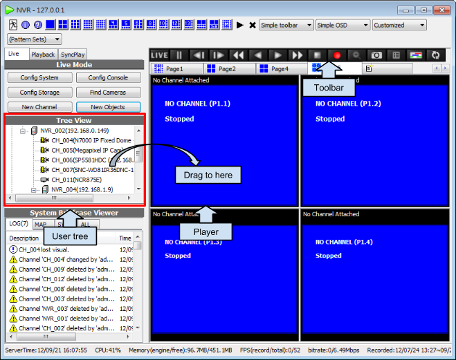
Before viewing live video, a channel must be attached to a player. To attach a channel, drag it from user tree(the red box above) to a player(the blue area above). Or double click to auto assign it to an available player.
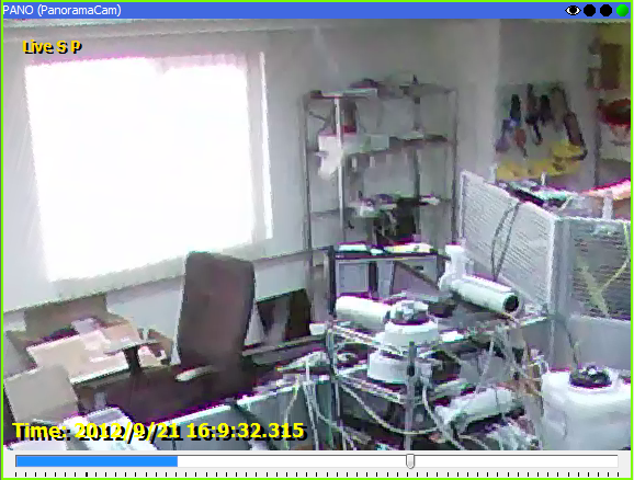
To switch from playback to live video, click LIVE(the leftmost) in the toolbar. Or when the player is focused, press ENTER on keyboard to view live video. Players can be focused by left mouse click on it. You can tell if a player is focused by a green frame around it.
Digital PTZ
Digital Pan-Tilt-Zoom
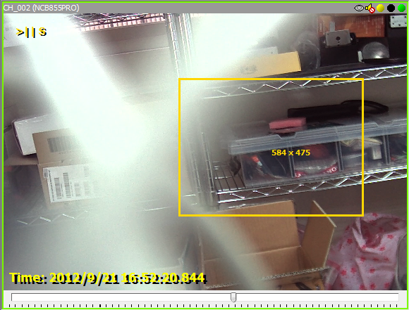
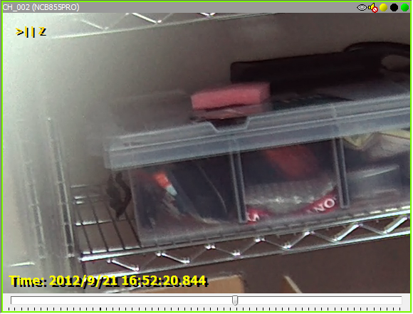
User can right-click context menu and select "Zoom-In" to drag a rectangular area to zoom-in.
Step 1. Click on the magnifier icon on the player toolbar.
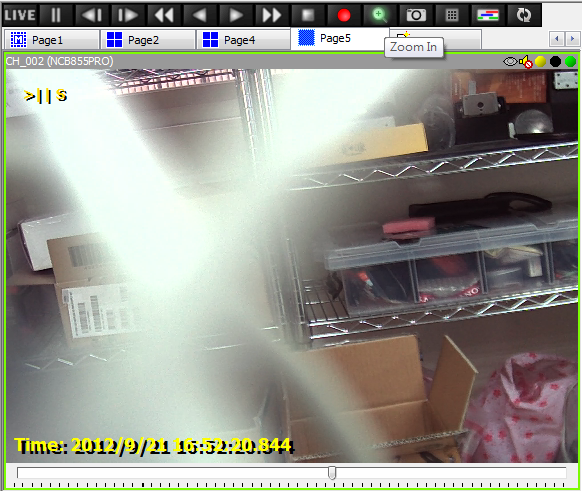
Step 2. Drag to select a rectangular area.
Step 3. Zoomed-in.
Under the zooming mode, user can hold mouse left button down to pan the zoomed area.
User can also use mouse-wheel to easily zoom-in and zoom-out interested area quickly.
Rendering audio
GUI Overview
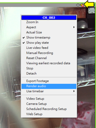
In the context menu of players, click "Render audio" to enable audio. To mute the channel, just click it again. Or click on the speaker icon.
Audio Icon Explained
Icon |
Description |
|
The channel has audio, and is currently playing. |
|
The channel has audio, but not playing. |
|
Though audio playing is requested, but no audio is available. |
|
Audio playing is neither requested nor available. |
Viewing playback video
Concept
There are several methods to view playback video. You can:
- Use the toolbar in player. It works just like the buttons on a CD/DVD player.
- Use player control panel.
- Use the timebar in player.
- Use the storage report.
- Hot keys

Console toolbar
Live view
Pause
Step backward
Step forward
Fast backward 2x/4x/8x
Backward playback
Forward playback
Fast forward 2x/4x/8x
Stop
Manual recording
Zoom in
Take snapshot
Open control panel
Toggle timebar
Synchronized playback
See also
Using playback timeline
Overview
A timeline is an integrated tool for both inspecting recorded data and navigating in video playback. The timeline can be configured to show different information of recorded data. User can access the desired data easily based on the information the timeline provides.
Using timeline
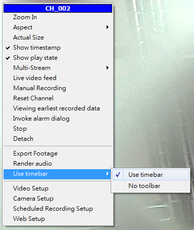
Timeline can be enabled in player context menu.
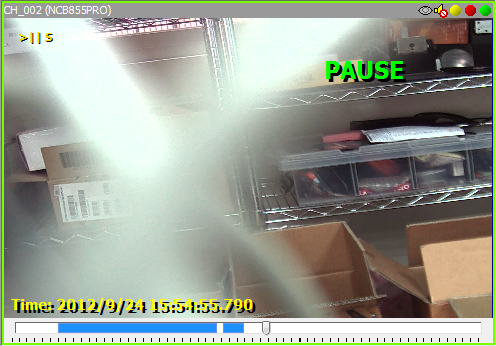
Before timeline can be operated, it must acquire window focus first. The user can use the mouse wheel to zoom in or zoom out the timeline. The ruler indicates the scale.
See also
Basic operations


Drag on the ticks to navigate in the timeline(the cursor changes to four-way arrow before you can do this). Use mouse wheel to zoom in/out. The ticks change automatically depends on the scale. You can also hover on the timeline to see the exact time.
There're four types of ticks. The black thin lines are for seconds. Black thick ones are for minutes. Red thin lines are for hours. Red boxes are for days.
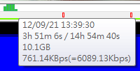
You can also select an interval by mouse dragging in the trackbar area. The interval length will be displayed.
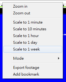
Fast navigation are also available in context menu.
Playback

You can double click on anywhere in trackbar area of the timeline to jump to that time point, or drag the arrow.
Timeline modes
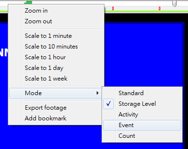
There are various modes in timeline to display different information. It can be set by right click on the timeline.
Type |
GUI Example |
Description |
Standard |
|
Blue area indicates that there are recorded data. White area means there's no recorded data. |
Storage level |
|
Green blocks indicates the storage level of recorded data. This is the average of a fixed timespan, which depends on the scale of the timeline. In this mode, user can calculate storage by selecting an interval. |
Activity |
|
The height of the orange block is the counts of activities in a fixed timespan, which depends on the scale of the timeline. |
Event |
|
Orange: activity Green: recording Purple: unexpected system off Gray: normal system off |
Counting |
|
The purple bar shows the level of tripwire counting. Results of all tripwires in this channel are summed up, including both directions of every tripwire. See also |
Synchronized Playback
Enable synchronized playback
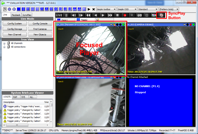
(note the green frame)
When synchronized playback is enabled, the play control of all players are synchronized. The video is synchronized to the focused player when playback is requested.
The timestamp of all synchronized channels may not match exactly. Because it's impossible for every channel to have available frame for any given time. This is obvious especially when the frame rate is low.
Synchronized Playback Tab
Synchronized Playback tab is very similar to synchronized playback button. Only it provides a date time control and a storage report to jump to specific time quickly.
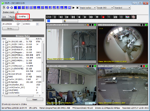
Specify a date and time then click “Go to...”, or browse and click the node in treeview, to jump to specific time.
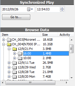
PTZ (Mechanical)
Basic operation
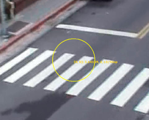
If a channel support PTZ and is attached to a player, users can hold left mouse button on it to start PTZ control. An yellow circle appears when the operation is valid. Hold mouse button and drag to the direction you want the PTZ camera to turn.
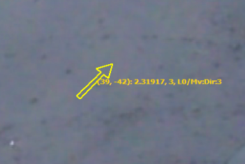
An yellow arrow indicates the direction and the speed to turn the PTZ camera. The camera turns faster when the arrow is longer. To stop the camera, simply release mouse button. To zoom in/out, use the mouse wheel.
Presets
Before you can use presets, you must first configure PTZ configuration. To invoke the configuration dialog, click PTZ config in player context menu. If there's no PTZ config item in the context menu, check the video config to see if the proper PTZ type is selected. For more information, check Video Configuration.
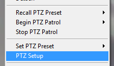
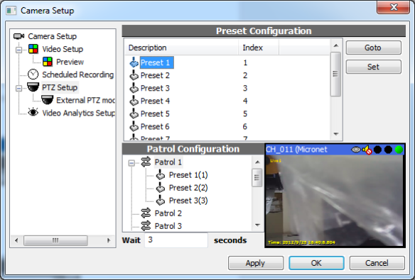
The description can be renamed by clicking on its description. Click OK when you done with configuration.
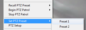
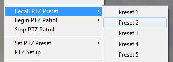
After PTZ is configured, you can use context menu of player to set or recall presets. Or use keyboard 0-9 to recall when the player is focused.
Patrol
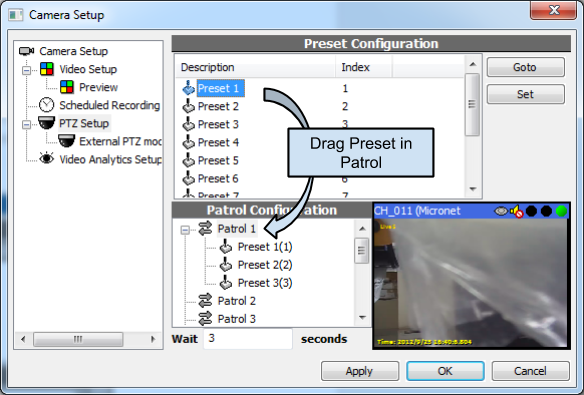
Patrol is a list of presets to be called in sequence. You can manage up to 10 patrols in the PTZ dialog.
The interval and speed of patrol can be set with “Wait X seconds”.
To add a preset in the patrol, drag it from Preset list and drop it in Patrol. Preset in patrol can also be dragged to change order.
<NOTE> PTZ functionality is limited by the actual specs and SDK support of the hardware. Not all models support the functions mentioned above.
Building user tree
Add/edit folders
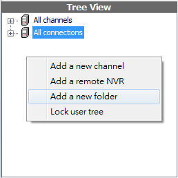
To add a new folder, right-click on blank area and click Add a new folder.
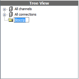
To edit folder description, click it again when it's already selected.
Add/edit tree items
To create a channel representative in user-created folder, drag a channel from folder All channels to the destined folder.
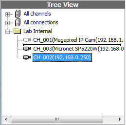
To change the order of items, drag and drop it in the tree.
Taking snapshot

To take a snapshot, click the camera button in the player toolbar. A message will be popped if the snapshot is taken.
Managing layout pages
Overview
A page is a set of players with its own layout settings and player state. Each page is configured separately and doesn't affect other pages. Users can create multiple pages and configure them for management purposes. For example, you can create a page named it "all channels". Switch its layout to 4x4 and attach 16 channels in it. And then create another page named "map". Switch it to 1x1 and open a map. Then you can switch between the two pages easily without open multiple windows or applications.
Add a new page

Click on the right most tab button to add a new page.
Editing pages
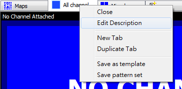
User can create, remove, and rename tabs in pattern tab control. Each pattern tab has its own layout and state. You can also drag the tab to change the order of the pages.


Tour
Design tour phases
You can use tab managing functions to create pattern pages and properly order them as the actual tour required.
Activating/stopping tour
Press F11 to toggle activating or stopping tour.
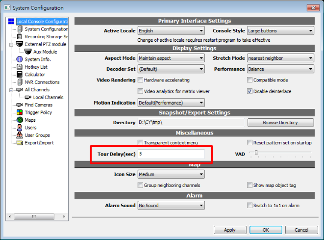
Configuring tour interval
Open the local console configuration dialog.
Storage report
GUI overview
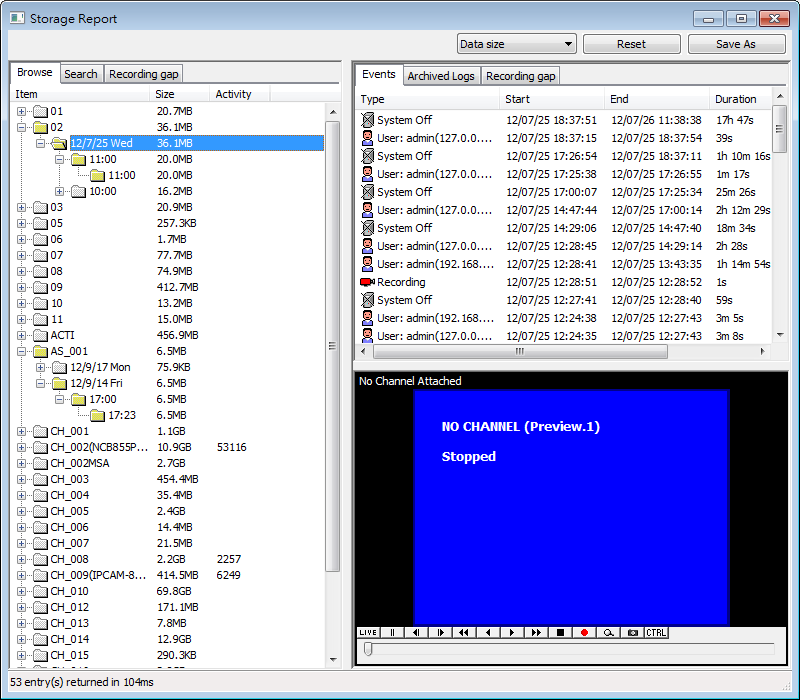
By using the subnodes of the root nodes, you can easily explore recorded video in the scale of days, hours, or minutes. The second column indicates the size accumulated of the item. The third is called the activity indicaton value. If this value is larger than more activity has happened during that period.
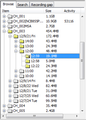
Event viewing
At right panel you can view the related events to the selected period of time. If you wish to examine the video of a specific event, you can either double-click the event to let an idle player to play it. Or that you can drag it to a specific player to play it.
Data size / data rate
Through the selection of the combo-box you can also change between viewing data size and data rate.
Resetting
After a long period of time of last query, or that the storage report stop refreshing latest data, you can click the "Reset" button to retrieve updated information.
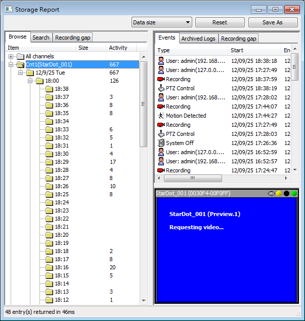
Intelligent Video Report
If one has properly configured intelligent detection (for example: double-tripwire counting), you can see additional nodes below the All Channels node. Try to open it to see detailed intelligent video report.
Event Search
To search event, click Search tab and the following page will appear.
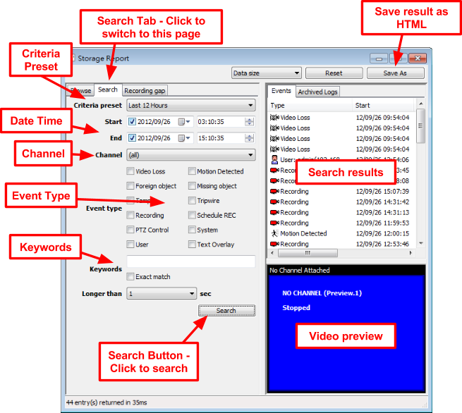
Use Criteria Preset to do quick search or specify the following criterias manually...
Channel |
Search all or one specified channel. |
Date Time |
Specify time span for the search. Both Start and End can be omitted. |
Event Type |
Search one or more types of events. |
Keywords |
Match keywords. Currently only Text Overlay and User support keyword search. |
Longer than |
Limit result to entries with duration longer than X seconds. This is useful to filter motion detection false positive. |
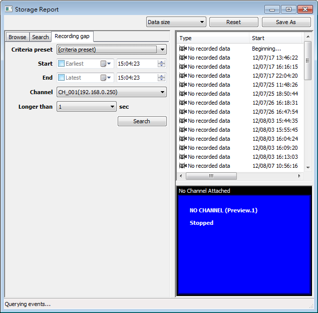
Recording Gap Search
Recording Gap is very similar to Event Search. It searches for timespan without recorded data. It’s useful to verify data integrity.
Alarm Dialog
GUI Overview
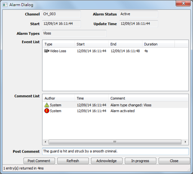
Concept
Alarm dialog provides the information of an alarm instance, which may consist of one or more alarm events. For each channel, there's always only one active instance. Any new alarm event is appended to the active instance. And the instance is deactivated once it's acknowledged. Inactive instance can no longer be modified, by user or by system. For active instance, user can change its state or post comment.
Open Dialog
There are few ways to open the dialog:
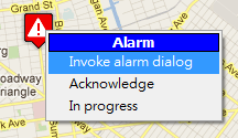
Player |
|
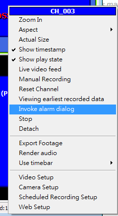
Use player context menu and select Invoke alarm dialog of player or press key "A". |
Briefcase Viewer |
|
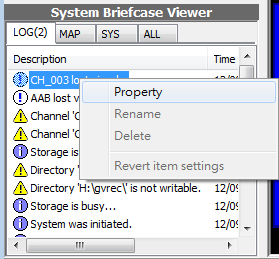
Use context menu of an alarm instance in briefcase viewer. Or use left-click menu if it's active. |
Map |
|
Left click on a channel with active alarm instance, in internal or external maps. |
Alarm Types
Type |
Description |
Vloss |
Video loss |
Tripwire |
Tripwire crossed |
Foreign |
Foreign object detected |
Missing |
Missing object detected |
Tamper |
Tamper detected (e.g. lose focus, spray, occlusion...) |
Alarm State
State |
Description |
Active |
Alarm is new and active |
InProgress |
Alarm is in progress. New alarm will reset the state to Active. |
Acknowledged |
Alarm is acknowledged and closed. |
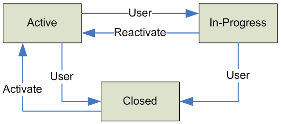
Alarm state transition diagram
Post Comment
User can only post comment of active or in-progress alarm instance.
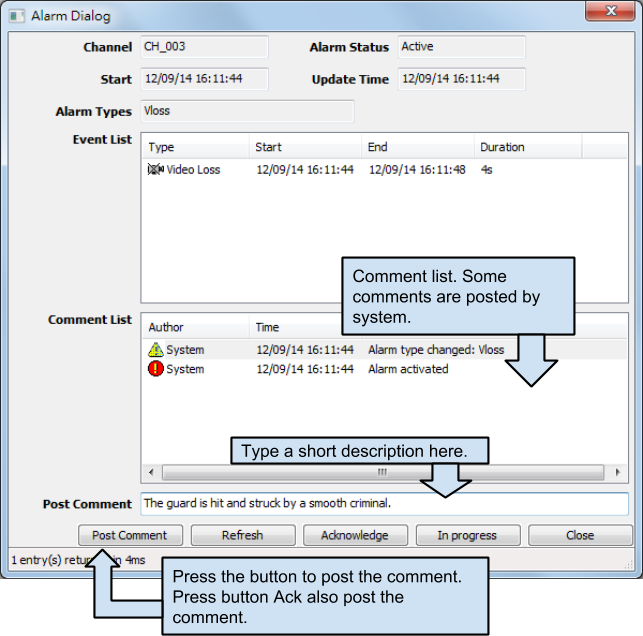
User calculator
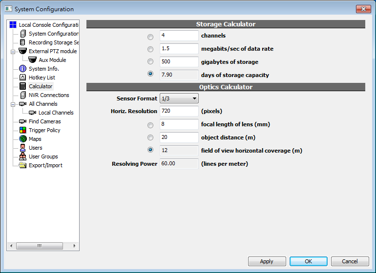
Storage Calculator
Users can input any 3 of the 4 variables. And the checked field will be calculated using the parameters provided.
Optics Calculator
For any calculation, sensor size and horizontal resolution of the camera must be provided. Please refer to the manufacturer's spec sheet of the camera. The user can provide 2 of the 3 variables; lens focal length, object distance, and horizontal coverage. The checked field will be calculated using the provided variables.
Sensor size
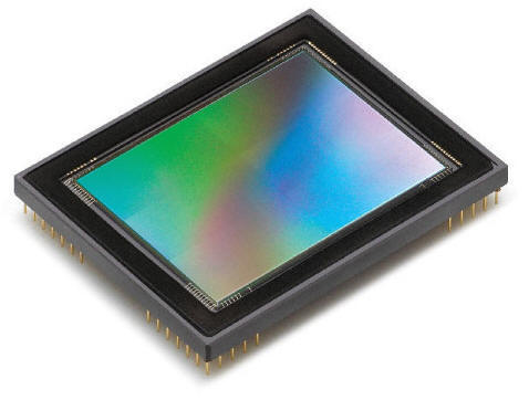
Please refer to the spec sheet provided by the camera manufacturer.
Horizontal coverage
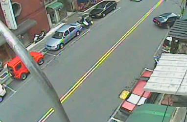

XXX meters
You can input lens focal length and object distance to let the system calculate the coverage, or vice versa.
Resolving power
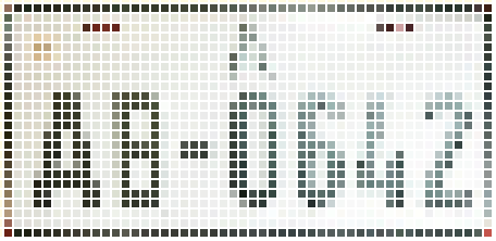

110 vertical scan lines per meter
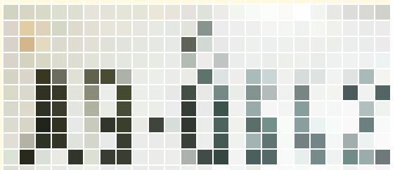

55 vertical scan lines per meter
Resolving power is a measurement of how many details can be seen in real world. The more the resolving power is, the more easier to identify the object. It can be used as a reference to determine if something can be identified or read. For example, about 100 lpm (horizontally) minimal is required to read car license plates. However, the value is just for reference as there are other factors affecting image quality as well. For example, weather, shutter speed, and focusing.
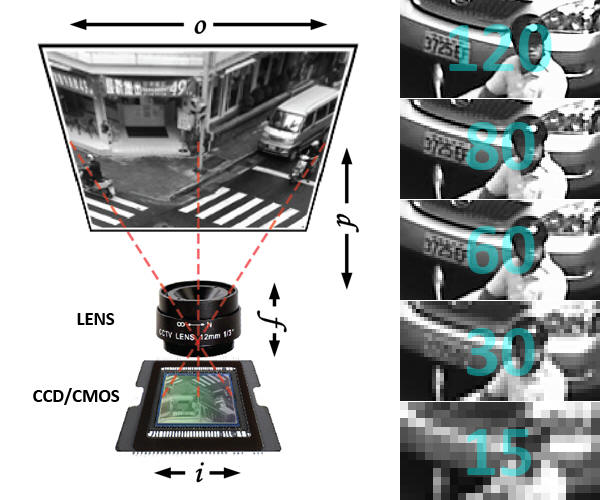
Diagram Explained
Legend |
Description |
o |
Width of field of view (in meters) |
i |
Sensor horizontal resolution (in pixels) |
d |
Object distance (in meters) |
f |
Focal length of lens (in mm) |
i/o |
Resolving power (lpm, vertical) |
Viewing logs
GUI Overview
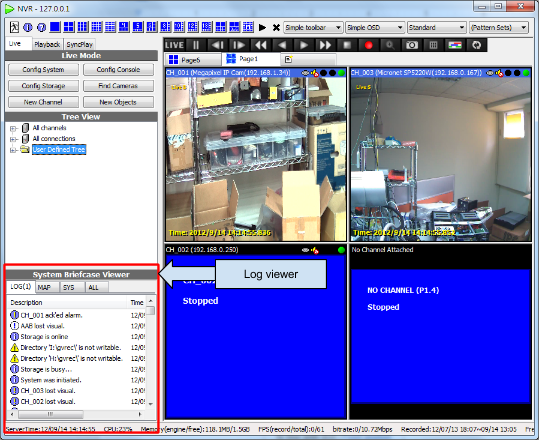
Logs can be browsed in system briefcase viewer.
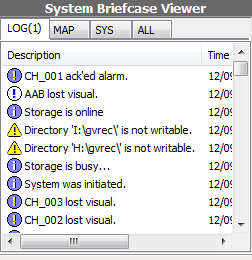
To make it easier to read, click on the tab to show certain types of items only.
See also
Console setting
GUI overview
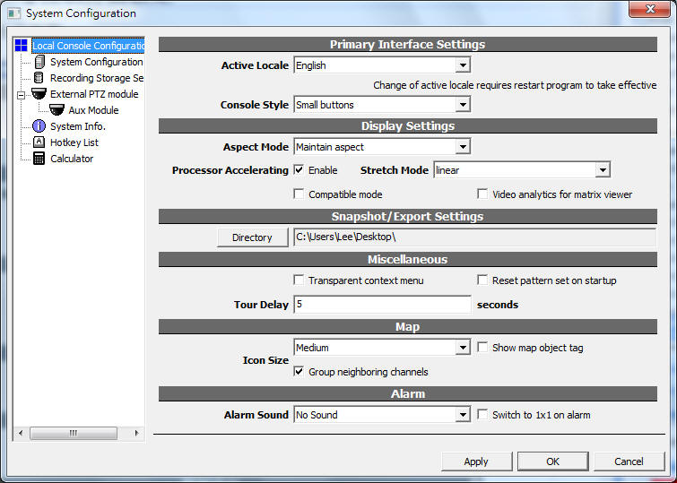
Display Settings
Aspect Mode
The video is not always fit perfectly in the player. It may be too wide or too tall. The player will display the video depends on this setting.
|
Maintain aspect |
|
|
Stretch video |
|
|
Crop to maintain aspect |
Processor Accelerating
Enable Intel MMX, SSE, and SSE2 processor accelerating functions. 3 modes are available. Nearest neighbor has best performance and Cubic offers best graphics quality.
Disabled(Windows GDI) |
Nearest neighbor |
|
|
|
|
Linear |
Cubic |
|
|
Compatible mode
Disable all graphics accelerating to solve display problems. The following are solutions for possible display problems. If the solution doesn't work, use Compatible mode.
Problem |
Recommended action |
Video card doesn't support DirectX 9 |
Replace the video card |
DirectX is not installed |
Download DirectX 9 from Microsoft |
* Use compatible mode only if some display problem is encountered.
Snapshot/Export Settings
Currently only JPEG is supported.
Miscellaneous
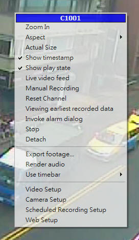
Transparent context menu
Reset pattern set on startup
See also
Tour Delay
See also
Map
Show map object tag
Display tags for channel objects in maps.
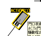
Group neighboring channels
With this option on, overlapped channels are represented with a G icon. Click on the icon to zoom in and see grouped channels.
Example |
Option |
|
Grouped channels |
|
Not-grouped |
Alarm
Alarm Sound
Play sound upon alarm.
Switch to 1x1 on alarm
When alarm is triggered, switch the channel to 1x1. Even if the channel is not currently viewed, it's forced to display.
Exporting footage
Using timeline
When a time interval is selected in timeline, export footage dialog can be invoked in its context menu to export the selected time interval.
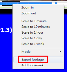
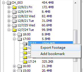
Using Storage Report
The dialog
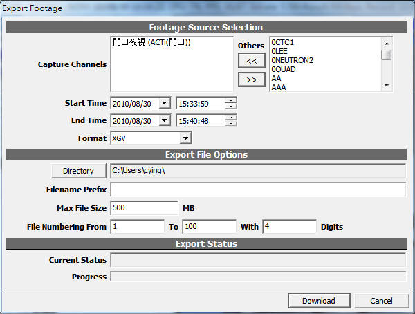
Field |
Additional Description |
Capture channels |
The left list are the channels to be exported and the right are the available channels. "Genius Vision NVR" support multi-channels exporting. |
Start time |
|
End time |
|
Format
|
XGV is "Genius Vision NVR"'s proprietary format. Select AVI if you wish to play the video in other video players. No player is guaranteed to be able to play the exported video as codec installed on a computer varies. For a list of audio/video codecs supported in AVI export, please refer here. |
Directory |
|
Filename prefix |
|
Max file size |
If the exported data exceed this limit, it's divided into multiple files. When using storage media with small space such as CDs or floopy disks, this must be set. |
File numbering from |
If exported data is to be divided using Max File Size, the files will be named in sequence. You can also fix the length of the filename by setting the digits. For example: with 4 digits, the files will be named as prefix0001, prefix0002, prefix0003... |
Current Status |
Indicates if the exporting is started, paused, or cancelled. |
Progress |
|
See also
Hotkeys
Enable hotkeys
To enable hotkeys, you must first focus on a player. To do so, left click on the player you want to operate.
See also
A detailed list can be found in System Configuration dialog, Hotkey List tab.
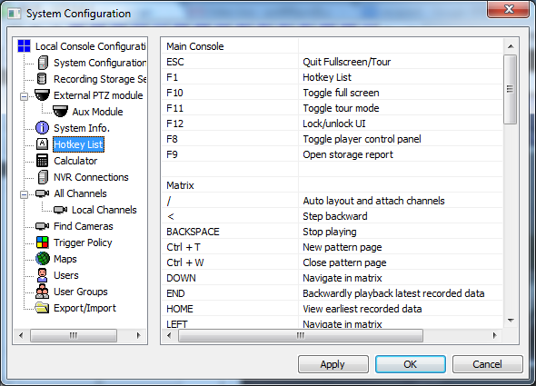
Basic operations
Key |
Function |
↑(Up arrow) |
Move player selection up |
↓(Down arrow) |
Move player selection down |
←(Left arrow) |
Move player selection left |
→(Right arrow) |
Move player selection right |
~ |
Select first player |
- |
Play slower (/2) |
= |
Play faster (*2) |
Enter |
Live |
Space |
Pause |
[ |
Playback backwardly |
] |
Playback forwardly |
< |
Backward step |
> |
Forward step |
Insert |
Take snapshot |
F8 |
Toggle player control panel |
F10 |
Toggle full-screen |
F11 |
Toggle tour |
F12 |
Toggle operator-lock |
PTZ operations
Key |
Function |
1-9, 0 |
Recall preset |
Ctrl + 1-9, 0 |
Set preset |
Ctrl + ←→↑↓ |
Pan, tilt |
Ctrl + PageUp |
Zoom in |
Ctrl + PageDown |
Zoom out |
Ctrl + Home |
Focus far |
Ctrl + End |
Focus near |
Remote live viewing
Synopsis
Genius Vision NVR provides a built-in web server to provide authorized and licensed remote user to view live video through Internet Explorer.
Configuring web server
Open the system configuration dialog box.
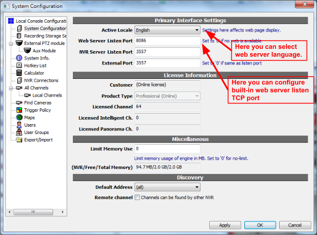
Default built-in web server listen port is 8086. If you configure the listen port to zero ("0"), the web server will be turned off.
Attention: Used TCP Ports
Please be noted that to make the remote live video web viewing, you are required to properly configure your firewall, if any. Two ports are needed. One is web server port, the other is NVR communication port, which defaults to 3557.
Broadcasting integration
When a vendor is properly licensed with GvLiveX SDK (by signing the "SDK Licensing Terms" document), he could integrate the provided ActiveX control into customized web pages to provide live audio-video broadcasting services.
If further information about SDK is required, contact us for more information.
Memory Watchdog
Memory Watchdog Overview
Memory watchdog is designed to combat unknown memory accumulation problems (a.k.a. memory leak). Memory accumulation could potentially make the engine (server) process to hang, which causes software watchdog unable to work (Existing software watchdog works only by monitoring server crash. If server didn't crash, software watchdog won't be effective).
Note: "Memory accumulation" problems could be caused by improper configuration of server, overload of the system, or software bugs.
To enable memory watchdog, set a proper value to "Limit Memory Use" box. This value defines the maximum engine process usage. If the engine process reaches this limit, it will automatically restart.
This value should be configured carefully according to the actual memory usage of your engine process (displayed below the Limit Memory Use value). Three times of average memory usage may be appropriate. For example, if your engine process uses 200MB in average, then you can set a value of 600MB. (By configuration 600MB of Limit Memory Use value, you instruct the memory watchdog to automatically restart the engine when memory usage reaches 600MB.)
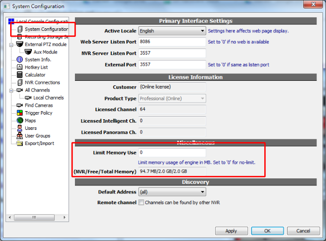
IO Port
GUI Overview

To access IO ports, expand a channel node in User Tree. Gray nodes are inactive ports. Red ones are active input. Green ones are active output. If a node is unexpandable, it doesn't support IO ports or it's not configured properly.
See also
Control
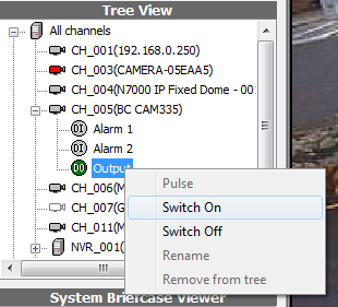
To control IO ports, right click on it to access the menu. Input ports cannot be controlled in the NVR system. They are connected to physical input devices such as switches, sensors... etc.
Pulse is a sequence of repeated on/off send to the port. Literally the controlled device will blink for few seconds. The final state is off.
IO Ports in Maps
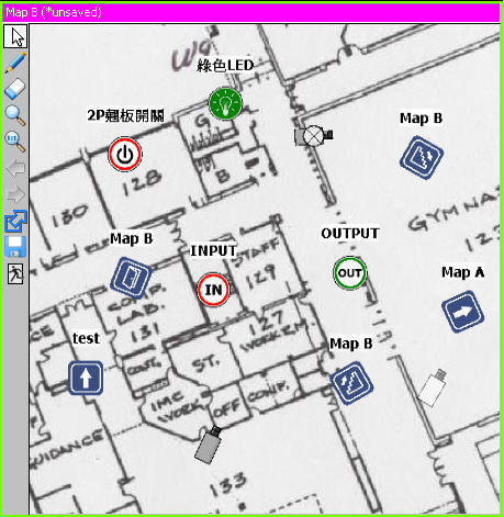
To add an IO port in map, drag it in map and release.
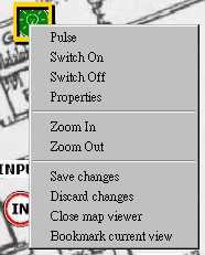
Use context menu to control the port.
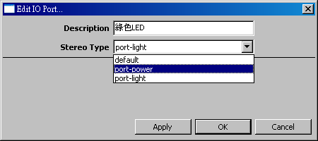
The description and icon can be edited in the property dialog. The change is only applied to the selected map item, not every item/node representing that port.
Player Control Panel
Concept
Player control panel is an integrated controller to control the currently focused player. Press F8 in the player to open the player control panel.
For more information about player and focused player, see also
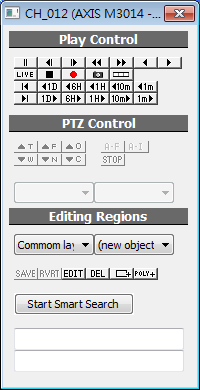
“Play Control” Buttons Explained
Pause |
Step backward |
Step forward |
Fast backward 2x/4x/8x |
Fast forward 2x/4x/8x |
Backward playback |
Forward playback |
Live view |
Stop |
Manual recording |
Take snapshot |
Frame skip mode |
|
|
View earliest recordings |
Jump backwardly for 1 day |
Jump backwardly for 6 hours |
Jump backwardly for 1 hour |
Jump backwardly for 10 minutes |
Jump backwardly for 1 minute |
|
Backwardly playback latest recordings |
Jump forwardly for 1 day |
Jump forwardly for 6 hours |
Jump forwardly for 1 hour |
Jump forwardly for 10 minutes |
Jump forwardly for 1 minute |
|
“PTZ Control” Buttons Explained
These buttons are only available for channels with PTZ support.
Zoom in optically |
Focus Far |
Aperture Open |
|
Stop |
Zoom out optically |
Focus Near |
Aperture Close |
|
|
“Editing Regions” Explained
Editing Region is an advanced function for video analytics applications. Refer to Region Configuration for more information.
Combobox Explained
Visual layer selection |
Object creation drop-down menu |
Buttons Explained
Save changes |
Discard unsaved changes |
Open region properties dialog |
Remove selected region |
Add a new rectangle |
Add a new polygon |
Pattern-save Functions
Save pattern templates and pattern sets
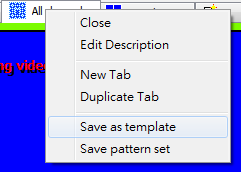
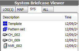
Action |
Description |
Save as template |
Save current page as a template. The template can be accessed in system briefcase viewer. |
Save pattern set |
Save all pages and their states as a pattern set. |
Pattern Set
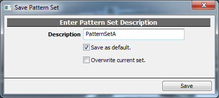
Saved pattern sets are added to the pattern set list in the local console. Click any pattern set to load. Current pattern layout will be overwritten.
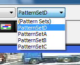
If Reset pattern set on startup is enabled in console setting, the first in frequently-used layout is always loaded when local console is invoked.
Player
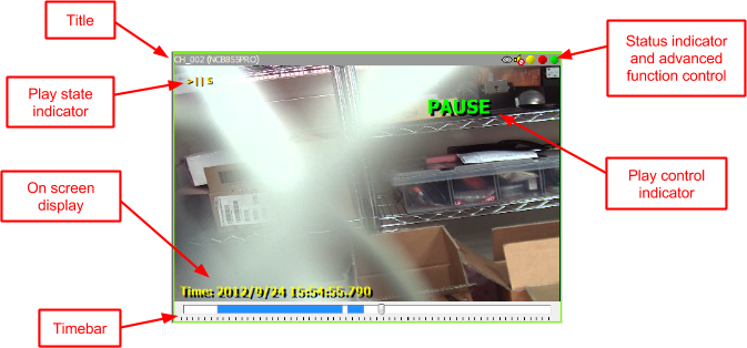
Title
Displays the name and description of attached channel/map. The background color indicates the status.
Outlook |
Description |
|
Nothing is attached |
|
Channel live view |
|
Channel playback/Map is loading |
|
Map is loaded |
|
Map is changed and not saved |
|
Blinking: Active alarm Static: Alarm in progress |
Play state indicator
Indication |
Description |
Live |
Live view |
||< |
Pause, backward play |
>|| |
Pause, forward play |
< |
Play backwardly |
> |
Play forwardly |
<< |
Fast backward |
>> |
Fast forward |
E |
End of recorded data |
AZ |
Actual size, zoomed |
A |
Actual size |
Z |
Zoomed |
S |
Stretched |
C |
Cropped |
OSD
Display the video time, resolution, and frame rate. Depends on OSD setting selected.
1 |
Play state indicator |
4 |
Input frame rate (frames per second received from camera) |
2 |
Data rate |
5 |
Output frame rate (frames rendered on screen) |
3 |
Resolution |
6 |
Codec |
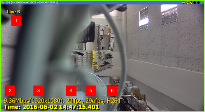
See also
Timebar
See also
Status indicator

|
Video streaming |
|
Recording |
|
Accessing disk |
|
Intelligent Detection: Inactive |
|
Intelligent Detection: This player is actively detecting motion |
|
Intelligent Detection: Detected by other player (server or other client) |
|
Intelligent Detection: This player is actively tracking object |
|
Audio: Off and not available |
|
Audio: On but not available |
|
Audio: Available but off |
|
Audio: Available and on |
|
Audio Output: Actively transmitting |
|
Audio Output: Muted |
|
Audio Output: Activate but not transmitting (no signal from microphone or not loud enough) |
|
Watermark: Vandalized |
|
Watermark: Authentic |
(some indicators are hidden if the function is not available)
Indicator explained:
Intelligent video |
Render audio |
Accessing disk |
Recording |
Video streaming |
See also
Part III: Intelligent Video and Advanced Topics
Activating Intelligent Detection
Activating/Deactivating Detection
If you wish to start intelligent detection, you need to activate the detection mechanism in addition to proper configuration. This step is necessary since detection consumes client CPU resource.
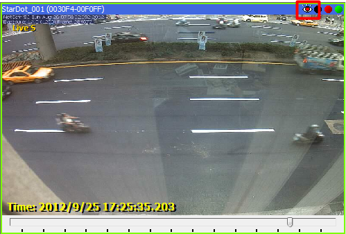
Icon semantics is as follows:
Icon |
Description |
|
Channel is not detecting |
|
Channel is detecting locally |
|
Channel is not detecting locally, but has been activated for detection somewhere else. |
Region Configuration
Select Video Analytics Setup tab in Camera Setup dialog.
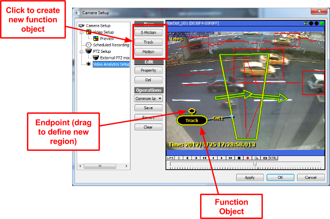
Region Configuration (Legacy)
Basics of region configuration
To configure regions, you need to invoke "Player Control Panel" by pressing F8.
Following window will appear:
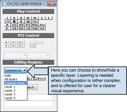
Now to explain the "Player Control Panel" functions:
Button |
Description |
|
Deleted selected object. |
|
Edit function object properties. |
|
Restore the modified region configuration into last saved one. |
|
Save current region configuration. |
|
Add polygon region object. |
|
Add rectangular region object. |
Function Object
Overview
Function Object is a abstract object defines a IVS function. It contains parameters and can be associated with regions to define ROI or object size. The following function objects are available in the system:
- Motion detection (hardware)
- Software motion detection
- Object tracking
Creating Function Objects
Invoke Camera Setup dialog and select Video Analytics Setup tab, then click on one of the New Function Object button.

Use context menu to configure Function Object.
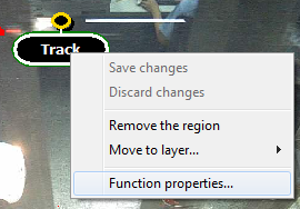
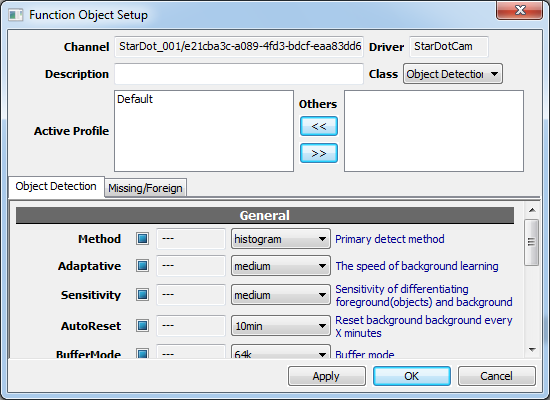
Define Regions
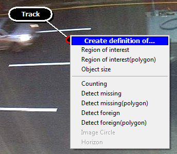
Drag the endpoint of Function Object to define regions as extra parameter. Available regions depends on the type of the Function Object.
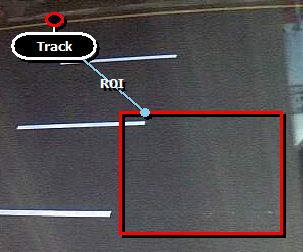
A tag will be displayed on the connection to indicate what the region is used for the Function Object. In this case, it’s defined as ROI (region of interest).
Intelligent Detection Basic Knowledge
Sensitivity |
The ability to detect an event in real world. |
Specificity |
The ability to ignore unwanted event in real world, i.e., shadow, lighting, leaves... |
False positive |
The system report an event but there’s actually no event in real world. |
False negative |
A real world event occurs but the system does not report it. |
Background |
The image that represents the scene. In IVS system it’s a statistical model beyond human understanding. |
Foreground |
The result of a video frame subtracts background.
|
Artifacts |
Compression generated glitches in video. It’s more severe with higher compression rate (lower bit rate).
Note the mosaic pattern in right image. |
MPEG based codec |
MPEG based codecs include MPEG4 and H.264. Image quality fluctuates in these codecs and artifacts accumulate over time until next I-Frame. This is a challenge for intelligent detection, especially when GOP size is very large, or bit rate is very low.
These 2 video frames differs only in hundreds of milliseconds. Note the artifacts (mosaic) in the gray area changes dramatically when I-Frame is received. This may generate false positive if sensitivity is set too high. |
Motion Detection
Definition
“Motion detection” function detects pixel changes in live video. At certain level of accumulated pixel changes, motion are reported. The generic algorithm used to perform motion detection does not distinguish foreground from background, thus it cannot segment object from other objects.
Configuration
See also
Parameters of S-Motion
“S-Motion” stands for “software based motion detection” and is implemented Genius Vision NVR software.
Right-click on the S-Motion function object to invoke following parameter dialog:
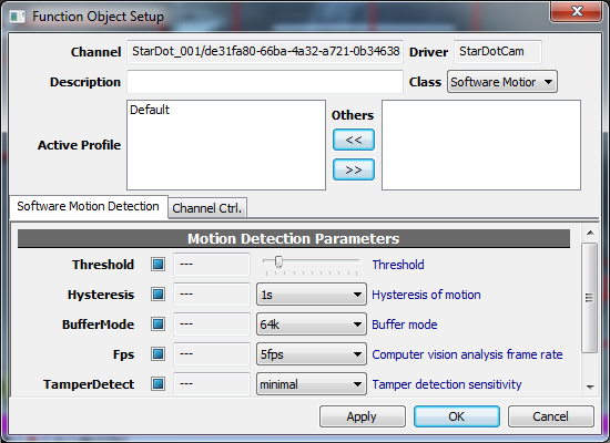
Threshold
Pixel will be considered being changed if the value difference between video frames exceed this threshold. The higher the threshold, the lower the sensitivity is.
Hysteresis
Hysteresis is the ability to accumulate states in the past few seconds. This function is to fight video glitch which lasts only 1 or 2 frames, in a timespan of milliseconds. Longer hysteresis decreases sensitivity and increases specificity. This function is especially useful for MPEG (H.264 included) based codec, which generates artifacts over time before next P frame.
TamperDetect
Performs video tamper/sabotage detection against sudden scene change, camera lose focus, camera blocking, or abnormal noise, etc.
Note:
1. S-motion must be accompanied by to Activating Intelligent Detection work properly.
2. Hardware-based motion detection requires both hardware and software support. Not all models of cameras are supported.
Object Tracking
Definition
Object tracking analyzes video sequence, isolates background (still objects) and foreground (moving objects), and then further track foreground objects to perform object trail tracking, directional counting, standing still detection (loitering), missing object, and foreign object detection.
Configuration
An example of object tracking configuration is as follows:
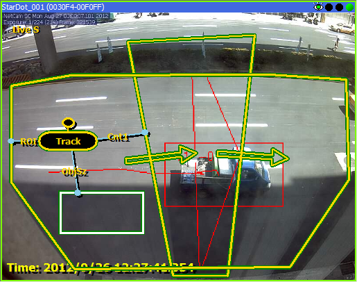
Explained as table below:
Link |
Description |
ROI |
Region of interest of detection. |
ObjSz |
Object size specifier. |
Cnt |
Object counter (with direction) |
DetectForeign |
Detects foreign objects |
DetectMissing |
Detects missing objects |
- If ObjSz is not specified, the system will assign a default object size automatically.
- If ROI is not specified, the entire video screen will be used as detection area.
Parameters (Object Detection)
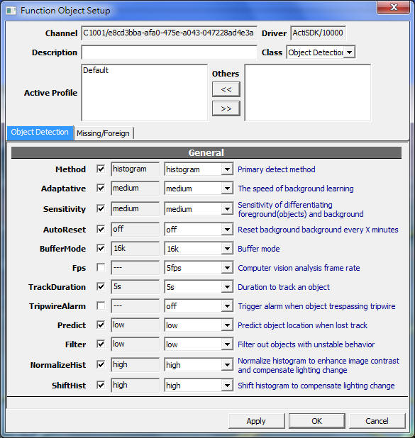
Method
Primary method (algorithm) used to perform object tracking. This parameter affects CPU and memory usage. Also potentially different methods perform differently on different scene.
Value |
Description |
histogram |
High accuracy. More memory usage. |
norm_dist |
Less memory usage. |
feature |
Only applicable to very specific scene. |
Adaptative
The rate of learning background. When objects hold still for a long time, they will be treated as part of the background. This parameter affects how fast a still object to be blend in background. When still object detection is a less requirement, configure this parameter to a higher value to increase background learning speed to prevent scene-change induced error rates.
Value |
Description |
high |
Objects hold still for 10 seconds will be considered as background. |
medium |
Default value. Objects hold still for about 1 minute will be considered as background. |
low |
Can detect objects hold still for a long time. (More than 10 minutes) |
Sensitivity
Sensitivity to differentiate foreground and background pixels. Higher sensitivity means better detection rate, but also more false positive.
AutoReset
Auto reset background every X minutes. In environments with inconsistent lighting, auto reset background periodically may improve tracking and reduce false positive.
BufferMode
The internal image buffer size used to perform computer vision algorithms. Lower size consumes less memory but may lose track of small objects.
Fps
Detection frame per second. This parameter affects the accuracy and the CPU resource usage.
Value |
Description |
20fps |
Maximum computing resource usage, used to track high-speed objects. |
5fps |
Default value. |
1fps |
Minimum computing resource. May only detects slower objects. |
TrackDuration
Length of tracked object trail. This parameter affects tripwire counting and still object detection.
Value |
Description |
3s |
Track slower objects. |
1s |
Default value. |
200ms |
Must be paired with Fps=20fps, used to track high-speed objects. |
TripwireAlarm
Trigger alarm when tripwire is crossed.
Predict
When lost track, use the last position and speed of the object to predict its position in the following frames. This improves detection rate but generates more false positive.
Filter
Filter out objects with dramatic change in size, speed, or shape.
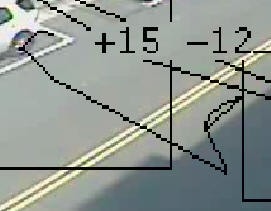
The object shown above jumps and is unlikely to be a real object. It's actually caused by the shadow and sunlight change. High filter setting decreases false positive.
NormalizeHist
Normalize histogram to enhance image contrast, thus improves detection rate. For image with very low contrast, this may enhance noise instead.

Left: original image, right: histogram normalized.
Contrast enhancing actually produces more artifacts than image features.
ShiftHist
Shift histogram to compensate lighting change. This is highly recommended for outdoor detection.
Same scenario with different lighting. Before the computer learns the new background, almost the entire scene is a very big object.
NormalizeHist and ShiftHist are especially useful for cameras with unstable metering system or inconsistent exposure.
Parameters (Missing/Foreign)
TimeMissing
Fire alarm if object is missing from pre-configured region after specified interval.
TimeForeign
Fire alarm if object is stayed in pre-configured region after specified interval.
Distributed Video Analytics
Overview and Rationale
The intelligent video detection architecture before branch b50 is pure client-side. This means video detection is actually performed in NVR client, rather than server. This architecture is sometimes argued as controversial, as explained in the following table.
Detection performed at client-side |
Detection performed at server-side |
|
Advantage |
1. Offload video detection from server. 2. Distributed computing load to (potentially) multiple clients, if available. 3. Detection result is visually accessible and verifiable. |
As long as server is on, detection is on. There can be no miss, even if no client is currently viewing. |
Disadvantage |
When no client is not viewing video, video detection is not performed. |
1. Increases server loading, making server a potential bottleneck. 2. Detection result is not visually accessible nor verifiable. |
From table above, it would appear that there is not a "best" between client-side or server-side detection architecture. It's simply a architectural judgment call. For flexibility, starting from branch b50, both server-side and client-side detection are supported. This allows wider options for user to configure the system to their actual need.
Video Analytics
There are 3 ways to do video analytics: by full-function player, matrix viewer, or server.
Detect by Full-function Player
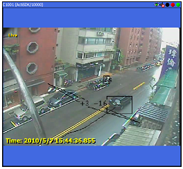
This is the most resource-consuming way to do video analytics. And it stops detection in video playback.
It can be turned on/off by clicking on the EYE icon at top-right.
Detect by Matrix Viewer
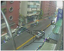
To turn on/off video analytics, configure it in Local Console Config dialog, under category Display Settings.
Player or Matrix Viewer video analytics can be done at remote clients; hence shares server loading.
Detect by Server
Server video analytics is indicated by the orange EYE-BALL on channel icon. There's no video rendering, and admin access is required to turn it off. So it's the most efficient and secured way to do video analytics.
To configure server video analytics, check Video Analytics Policy below.
Video Analytics Policy
Video analytics policy can be configured in
Camera Setup > Video Setup > Record > Miscellaneous > VideoDetect
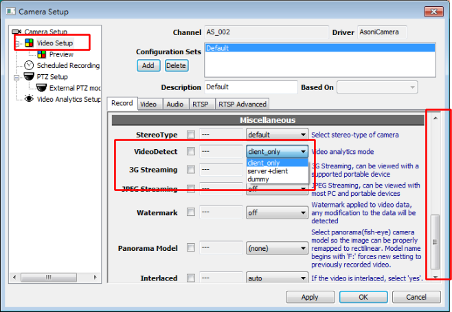
The meaning of VideoDetect choice is described below:
“VideoDetect” value |
Description |
client_only |
Only client(Full-function Player or Matrix Viewer) do video analytics. |
client+server |
Both client and server do video analytics. |
dummy |
This option is reserved for engineering debug. Do not select. |
When there are more than one video analytics instance, only first one is selected as final result for possible actions. The choice of detection instance is by first-in-first-out (FIFO) order.
Smart Video Search
To enable Smart Search, first switch to Playback Mode. Then focus a player and click Start Smart Search.
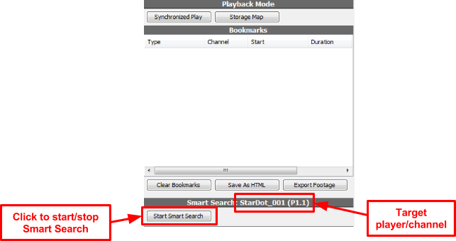
A Software Motion function object will be created by default. User can define additional region of interest or start playback right away to search entire scene. Search can be forward or backward, 1x/2x/4x or more. But generally it lost accuracy beyond 8x, especially for fast moving objects like automobiles.
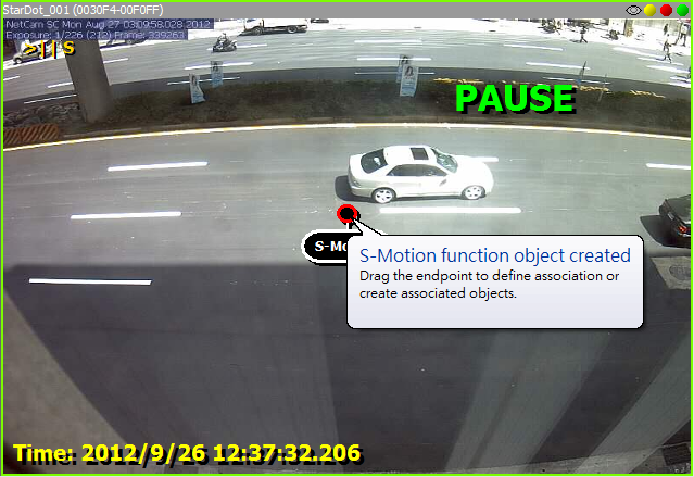
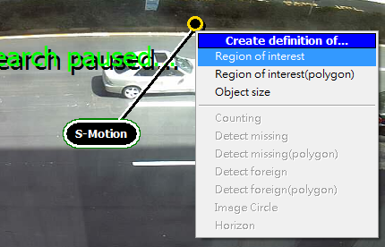
Search results will be saved as bookmarks. Click the bookmark and video will be displayed in Bookmark Preview. Right click on bookmark to change description or delete it.
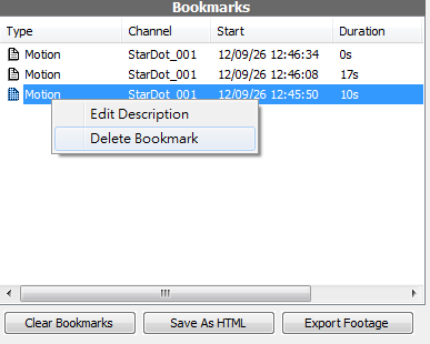
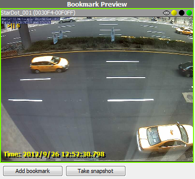
Smart Search support all intelligent detection functions. See also Region Configuration.
Using Panoramic Camera
Enable 360 Panorama
Panorama is not a standard feature. It requires additional license to be installed to activate. To activate, select one of the Panorama Model in Camera Setup dialog, Video Setup.
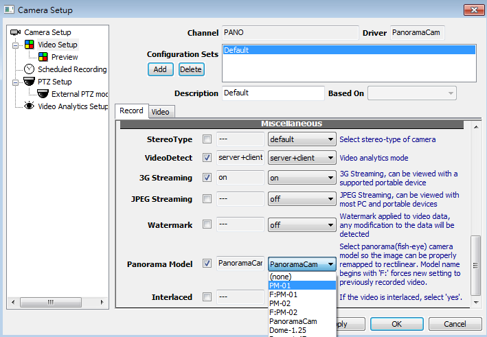
If there’s no options in Panorama Model, the license is not installed properly.
Calibration may be required. To calibrate, focus the player and press F8 to bring up player control panel. Create a “Panorama” function object.
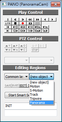
Panorama function object looks like this:
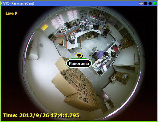
To calibrate image circle, drag the endpoint and define a Image Circle region.
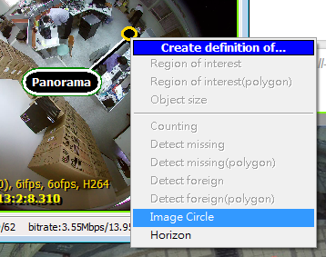
Carefully match the circle with the outline of panorama image. Expansion or contraction may be needed to get optimal result, as lens optics design varies. Click Save in player control panel to apply the setting.
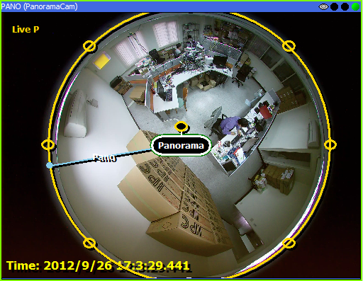
If configured properly, Panorama will be appear in context menu of player.
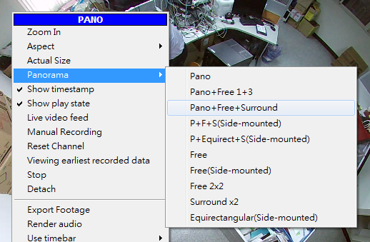
These are examples of Panorama modes:
- In rectilinear view, use mouse to pan/tilt/zoom. Operation is very similar to speed dome.
- Click in the original view (360° distorted) to jump quickly to the clicked location.
- Hold ALT to swap view. Only views with same aspect ratio can be swapped.

Converting Video to JPEG Stream
Concept
Some non-IE web browsers do not support ActiveX components provided by the NVR software. In such cases, online video or images can not be accessed; JPEG image format, on the other hand, is the world's most widely used image format. Our system supports JPEG online viewing for most browsers including those on the mobile phones. Some extra steps need to be taken to enable this feature.
Introduction
Suppose your NVR is 192.168.0.124, this URL http://192.168.0.124:8086/mjpeg/sdk.html will lead you into the following page (as illustrated in picture below). This page is a tool to generate single URL to a JPEG image or more sophisticated iFrame codes to be embedded in 3rd party web pages, or to generate QR code to be used with mobile device.
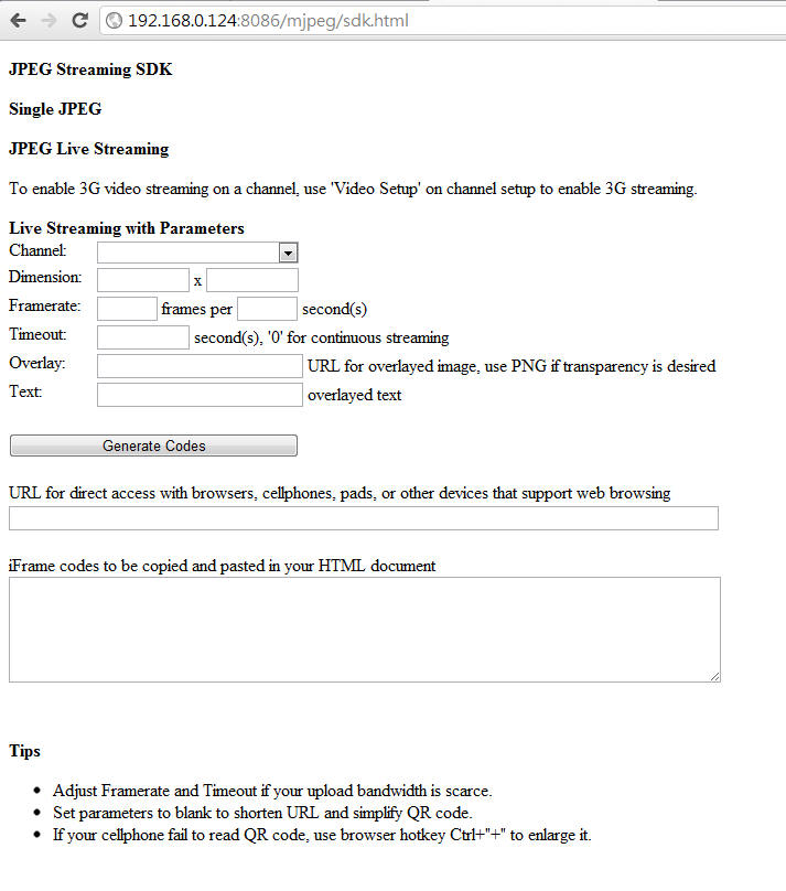
Enable JPEG Streaming
JPEG Streaming has to be enabled in Camera Setup before it can be accessed. Channel with JPEG Streaming enabled consumes hardware resource (CPU and RAM) on NVR server. So design the system carefully.
Take camera "aaa" as an example, right-click to select the Video Setup.
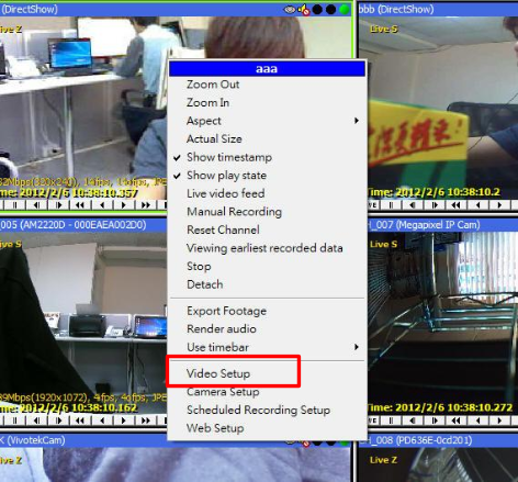
You need to make the following settings in Video Setup:
Change the JPEG Streaming to "on"
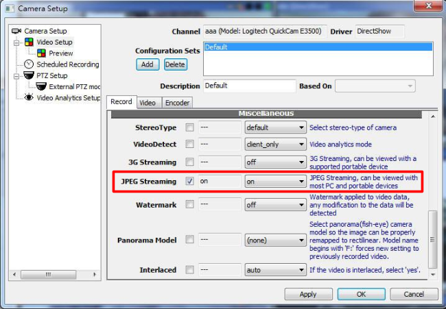
Single JPEG
Let's go back to the tool page, Camera "aaa" will appear in the list
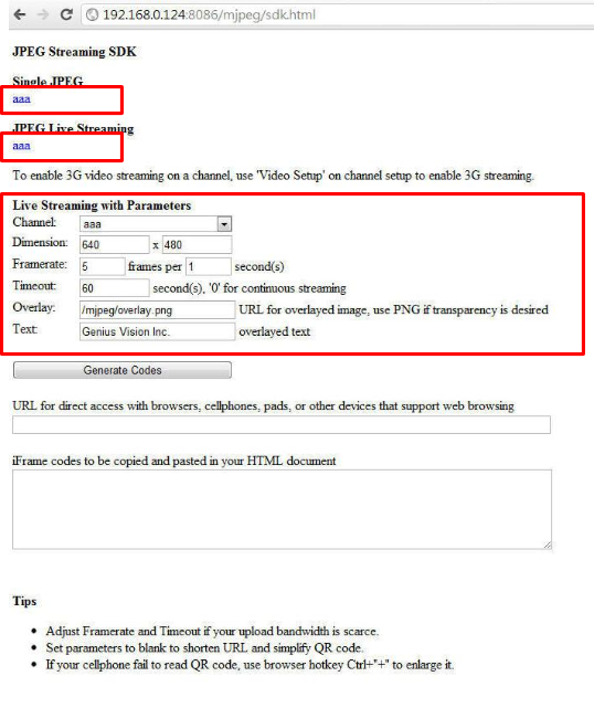
The link under the Single JPEG is a single JPEG image. Its URL can be referenced in a web page using <IMG> tag.
The link under the JPEG Live Streaming is real-time video contained in a predefined web page with JavaScript to update the image automatically.
Click to watch real-time image or video.
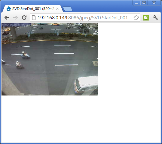
Multiple View
Connect to this URL to view all JPEG streams...
http://<ip_address>:<port>/mjpeg/multiview.html
It will be scaled automatically to fit in browser window.
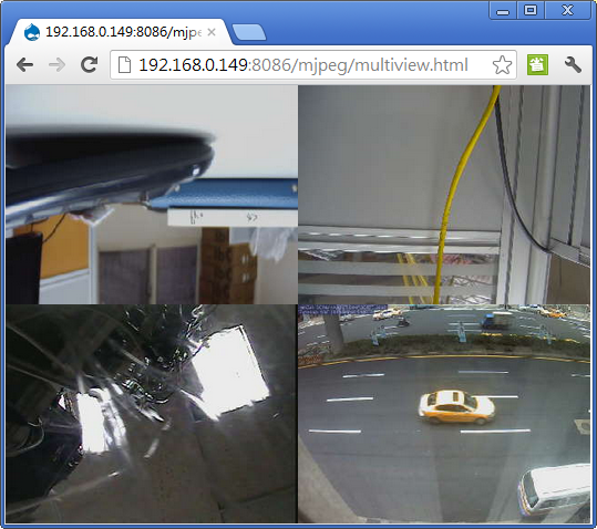
Embed Video In Web Page
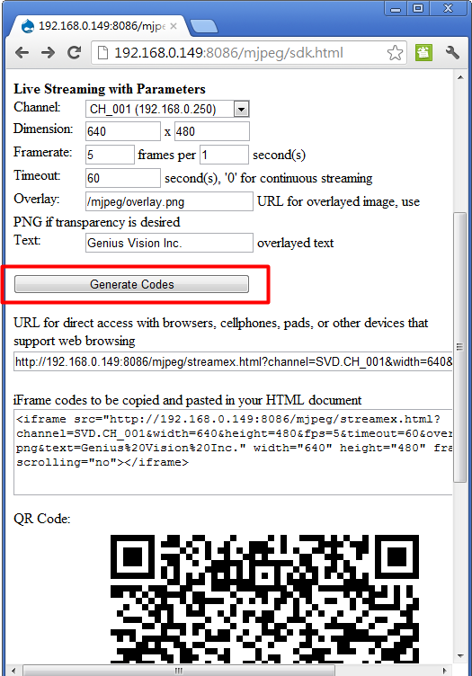
Click Generate Codes to generate HTML codes to be copied and pasted in web page using text editor or HTML editor. You need basic knowledge about HTML, web server, and public IP address to make this work. You may need to configure network switch and router properly or image cannot be accessed through internet. Consult your network administrator for more information.
The QR code cannot be referenced directly in HTML. You have to take screenshot and save as a image file on your web server.
System Safe Mode
Overview
Sometimes incorrect system configuration or corrupted environment can cause system unable to start. Under this circumstance, users cannot even enter the system and disable the problematic part of function so the system becomes a deadlock state. Safe Mode can come in handy to deal this kind of situation.
“Safe Mode” function
When Genius Vision NVR server is started in safe mode, it will incur following behavior changes:
- Storage drive will not be mounted or scanned
- All channels are in non-active mode.
Enabling “Safe Mode”
Right-click on the NVR tray icon and select “Config SafeMode...” to invoke safe mode configuration dialog.
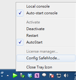
Following dialog will appear and offer selection
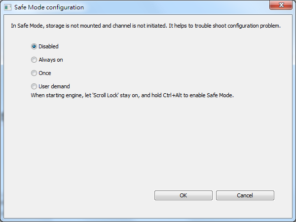
Options explained:
Option |
Description |
Disabled |
Not using SafeMode. |
Always on |
Use SafeMode, until turned off. |
Once |
Use SafeMode only for next system start. |
User demand |
When starting engine, let “Scroll Lock” stay on, and Ctrl+Alt to enable SafeMode. |
Availability
SafeMode is a relatively new function and only available since following versions:
- b70: Version 715.
Backup/Restore License
Note: This function is available since version 769.
Overview
Sometimes if the whole system is overwritten for some reason (reinstallation of the OS) or accidentally purges the entire software installation, the license information could be gone permanently. To prevent this from happening, you need to backup the license and restore it when needed.
Note: that you can only restore license to the same system (OS+computer hardware). Restoring to different system will render the license useless.
To use license import/export, select ‘Export/Import installed licenses’ and click Next..
.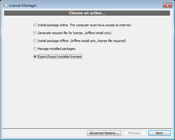
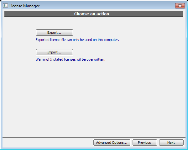
Export (Backup)
Input a filename and click Save..
.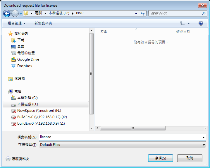
A message is displayed if license is exported successfully.
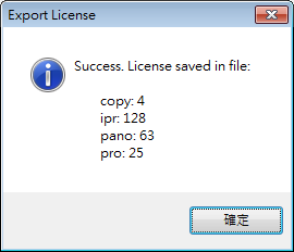
And Export button will be replaced with ‘Browse In Folder’. Click to browse the file in Windows file manager.
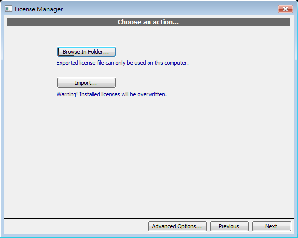
Import (Restore)
Select exported file and click Open.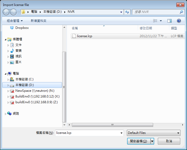
If there’s license already installed, a confirmation dialog is displayed. Click yes to proceed importing
.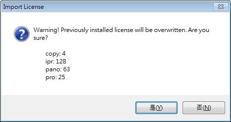
License manager has to be restarted to see imported license
.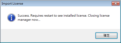
Page of


