 Example System / ONVIF実装方法のFAQ

リレー出力(ET01)の実装方法は
Translated: en=>ja from How to implement Relay Output (ET01)
NOTE: 申し訳無いがこの記事がまだ翻訳されているです。 この記事の緊急の必要がある場合は、私たちに連絡し、この記事の翻訳を迅速に行います。
Warning! This is an implementation hint article. Read this first.
Calling sequence
For ONVIF relay output function, the calling sequence of Genius Vision NVR can be summerized as follows:
- This sequence only applies when Event.Template (explained here) is set to ET01.
- Calls <device>GetRelayOutputs to obtain number of input and their tokens. If failed, NVR will try to call <ver10/deviceio>GetRelayOutputs. This automatic protocol version detection will be remember in an internal variable called RelayUseDevIO.
- Engage event notification sequence.
- If relay is operated by user to switch ON or OFF, NVR will call <device>SetRelayOutputState or <ver10/deviceio>SetRelayOutputState, depending on RelayUseDevIO.
Reflecting relay state change
Event definition in spec
ONVIF-DeviceIo-Service-Spec-v221.pdf
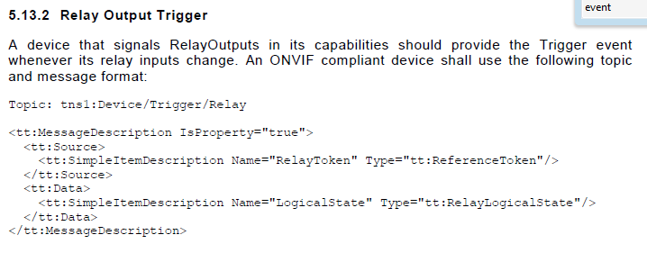
Message XML example
Relay output state is reflected using notification events.
<wsnt:NotificationMessage> <wsnt:Topic Dialect="http://www.onvif.org/ver10/tev/topicExpression/ConcreteSet"> tns1:Device/Trigger/Relay </wsnt:Topic> <wsnt:Message> <tt:Message UtcTime="2008-10-10T12:24:57.321Z"> <tt:Source> <tt:SimpleItem Name="RelayToken" Value="[relayToken]" /> </tt:Source> <tt:Data> <tt:SimpleItem Name="LogicalState" Value="[relayLogicalState]" /> </tt:Data> </tt:Message> </wsnt:Message> </wsnt:NotificationMessage> |
- [relayToken]: Must match one of the tokens returned by <device>GetRelayOutputs or <ver10/deviceio>GetRelayOutputs, depending on RelayUseDevIO.
- [relayLogicalState]: active or inactive, reflecting actual relay status.
Changing relay state
- Camera must implement <device>GetRelayOutputs or <ver10/deviceio>GetRelayOutputs in order to indicate its support to relay ouptuts.
- Camera must implement <device>SetRelayOutputState or <ver10/deviceio>SetRelayOutputState in order to be able to change relay state.
- The version of spec implemented by the relay output commands must be consistent.
関連項目